
- Project
SpidaBot (ESP32)
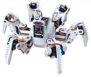
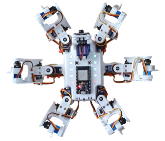
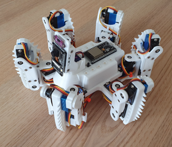
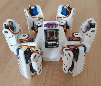
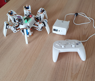
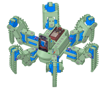
A hexapod robot, which has a video camera for streaming live video to your PC’s browser, or mobile phone, whilst it’s walking about, and a laser range finder to measure the distance of nearby objects. It uses quite powerful servo motors, and can be trained to perform intricate moves using the app I’ve provided. It’s controlled over Wi-Fi using a Wii Classic controller, with plenty of scope to add more features. ESP32 microcontrollers are great for projects like this.
Project Overview
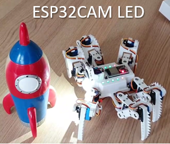
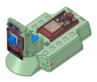
This project takes my previous Hexbot2 robot to a new level, adding more servos to the legs, for greater movement, and an ESP32-CAM on its pan and tilt head, so you can control it remotely whilst viewing its whereabouts. Controlled over Wi-Fi using a Wii Classic controller, enables you to control body and head movements independently, and gives you plenty of scope for tailoring movement options.
Over the Wi-Fi link a PC based app can easily be connected to display a large array of information screens, which is great for demonstrations. There is also a ‘Move Trainer’ in the form of a Windows, which helps you create those special moves, to impress others, and give you SpidaBot personality. The existing options can be easily tailored and extended by you. Check out the video link opposite.

|
|
||||
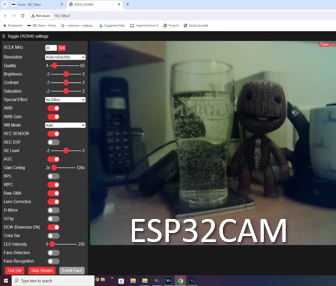
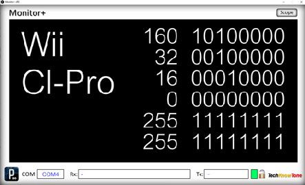
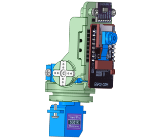
| The Tower Pro MG92B servo provides a massive amount of torque, for a servo motor of its size; giving the SpidaBot plenty of muscle power, when it comes to lifting its body high off the ground. The code in the walking sequence is relatively straightforward, allowing turning whilst walking, by adjusting the stride of the legs; and as it’s based on counters, the SpidaBot can record and display how far it has walked in a given direction. I’ve also included code for sideways walking, just like a crab; which allows it to steer on the move too. The VL53L0X laser range finder allows the SpidaBot to measure the distance of objects; so it’s able to demonstrate it’s response to approaching targets, and you could add autonomous code to this. This is the first project in which I’ve used an ESP32-CAM, and I have to say that for the price, it performs really well as a soft access point server, to which you can easily connect a Wi-Fi device, and view images in a web browser. The Wii controller can also turn on/off the cameras built in white LED. |
||||
|
|
||||
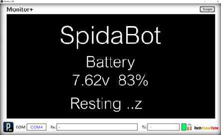
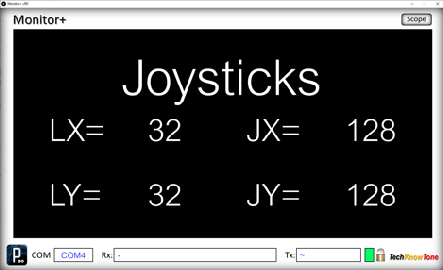
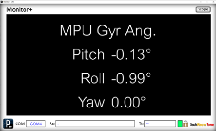
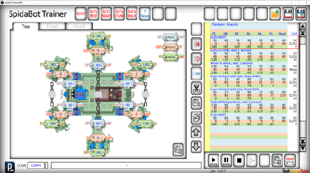
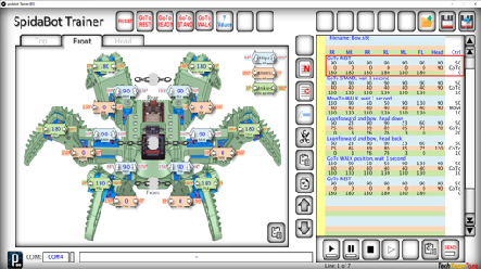
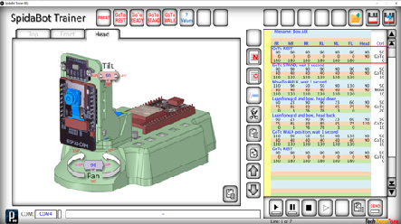
| This robot can be used in conjunction with a Windows laptop PC, on which you would run the provided Monitor+ app. This app was written originally to show what is actually being displayed on a 128x64 OLED display, but can also be used without the need for display hardware, This all works over Wi-Fi, and the screens presented are all generated by the code in the SpidaBot, and accessed by simply clicking on the displays screen. The Monitor+ app can also be switched into ‘Scope’ mode, in which it requests data from the micro and presents the data as waveforms, or numerical lists. In this project I’ve also included a ‘Move Trainer’ app, which enables you to move each, or several servos at once, and store their positions in a list, that can be played back by the SpidaBot. This makes the creation of complex moves possible, and you can simply copy and paste them into your SpidaBot code to react to button presses |
||||
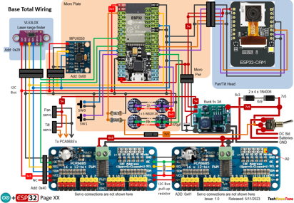
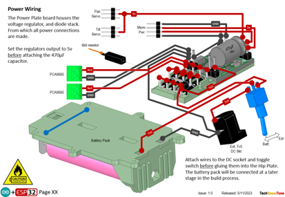
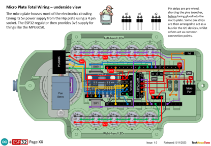
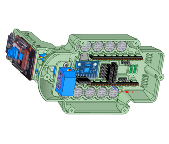
The circuit diagram shows the wiring of the SidaBot body. Given the large number of servos, there are insufficient pins on the ESP32 to drive them, so the design employs two PCA9685 16-channel drivers, which translate the values sent over the I2C interface to servo PWM signals. The servos simply plug into these boards, making their connections very simple to do
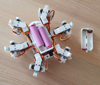
The SpidaBot code samples the battery voltage, at regular intervals, in order to predict battery capacity. Which is useful as some movements will consume quite a lot of power. But the 3000 mA hr 18365 Lithium batteries do a great job at keeping things going.
The orientation of the SpidaBot, obtained from the MPU6050, is currently used to measure turning movements, for demonstration purposes. But it could be used to detect and react to the effect of the SpidaBot walking over uneven terrain. That’s often done with toe switches; but not in this design, to make things simpler.
All of the 3-D models are provided as STL files, zipped together into one file. They can therefore be used with a slicing application of your choice, to create the g-code files for use with a 3-D printer. For my project I used PrusaSlicer, which is a great app and a free download from the internet. Models for assembly aids, and testing are also included.
I’ve also provided a pdf file showing you the names of each component and the quantities you need to print of each. The design is essentially held together using 2 x 10 mm self-tapping dolls house screws, making it strong and rigid, whilst still being able to take it apart, should you need to changed a component. The upper body, containing the micro, plugs into the lower chassis. So a different design of body and controller, could be added with relative ease.
I’ve not spent too much time designing an interestingly shaped head for Spidabot, as I try to show students the technology behind the scenes, but there is plenty of scope for you to do that. Equally you could change the design of it’s legs or body. Why not give your 3D modelling skills a challenge..
Design Files
The following files can be downloaded to help you complete this project. Each has a hyper-link and an associated description. Depending on how your web browser is configured the links will either open the files directly into the browser or offer them as downloads. Note that these documents only refer to the SpidaBot robot. You are likely to want to make the Wi-Fi D1 Transceiver project as well, and get a Wii Classic, in order to control it.
Circuit Diagrams- drawings of what is seen in the views above. Use it as a guide to wiring up your project. Updated: 26/11/2025.
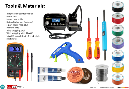
Parts list - the things you will need to build this project. You will also need to make the WiFi transciever project, found here..
3-D Models - a zip file containing all of the STL files, which you can use with a slicer application.
3-D Parts - a pdf file which identifies the 3-D parts, pilot drill sizes, and the quantities of each you will need to 3-D print.
Software Code - the all important .ino code file, which runs the project, and ‘Processing’ apps. See comments below on coding. Updated: vR2,10/05/2025
Calibration Record - explains the things you will need to accomplish to get the Uni-Bot self-balancing. Updated: 26/11/2025.
Demo Functions - a pdf outlining how you control the Uni-Bot robot. Updated: 10/05/2025.
Libraries
This project relies on the use of six libraries, <Arduino.h>, <HardwareSerial.h>, <Adafruit_PWMServoDriver.h>, <FastLED.h>, <esp_now.h>, <WiFi.h> in the SpidaBot code, which may need to be included in your version of the Arduino IDE set-up.The RGB LEDs are controlled using the FastLED functions and the Wi-Fi link relies on the use of the ESP-NOW protocol. Note that Tabs have been used within the IDE, to simplify editing, so there is a separate .ino file for each of the six tabs. All of which must be included in the SpidaBot_R2 folder, The code for the ESP32-CAM is held in a separate .ino file,
Design Notes:
The following notes will help you understand how the files in this project work or can be used in principle. Each note has a bold heading for quick reference and they are listed in alphabetical order.
Software Code- when you download this .zip file, and unzip it; the folder extracted contains several folders as follows:
Camera_SoftAP_R0 - .ino code files for the ESP32-CAM board.
Proc_16Ch_Controller_Win32 - a 16-channel controller app, compiled for older x32-bit PCs.
Proc_16Ch_Controller_Win64 - a 16-channel controller app, compiled for x63-bit PCs.
Proc_MonitorPlus_Win32 - a display monitor app, compiled for older x32-bit PCs.
Proc_MonitorPlus_Win64 - a display monitor app, compiled for x64-bit PCs.
Proc_SpidaBot_Trainer_Win32 - a movement trainer app, compiled for older x32-bit PCs.
Proc_SpidaBot_Trainer_Win64 - a movement trainer app, compiled for x64-bit PCs.
SpidaBot_R2 - .ino code files for the SpidaBot ESP32
Note that the .ino folders contain several files. This is because I use the tabbed interface of the Arduino IDE, which saves a separate .ino file for each tab. You need all of these files in the project folder for the code to compile correctly.
3-D Models - this design is based on the use of 2x10mm dolls house self-tapping screws. The models have 1.5 mm pilot holes for the self-tapping screws. The pdf file helps you identify all of the parts, and indicates pilot hole sizes.
Calibration Record - It is essential that you undertake calibration tasks, in order to enter the correct values into your .ino file. Otherwise the robot will not function correctly and could even result in damage and over-heating of the servo motors.
STL Model Files - all models are designed to be printed on a 3-D printer with a 0.4 mm nozzle, with slicer layer heights of 0.3 mm.
Need more?
If you feel that I haven’t included enough information to allow you to tackle a project of this type then send me an email explaining what you need. Or if you just want to give me some general feedback on this site, or to suggest projects what I might include which would be interesting to you, I’d be pleased to hear from you.
Page updated: 26/11/2025