
- Know How
Light Emitting Diodes (LED’s)
Discover how to use these electronic components in your Arduino projects.
Their small size, low cost, low operating voltage, low power consumption and the variety of colours available make LED’s very popular as lamps in Arduino projects. They are also highly reliable, if handled correctly and used in an appropriate manner. If used incorrectly however they may damage your Arduino micro-controller or become damaged themselves. Given their electrical characteristics they will, in most cases, require an additional component known as a ‘resistor’ in the electrical circuit to limit the current drawn by the device. We will firstly familiarise ourselves with the device, and then discuss electrical characteristics and circuits.
 |
||||||||||||||
|
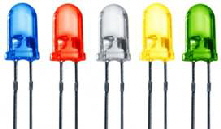
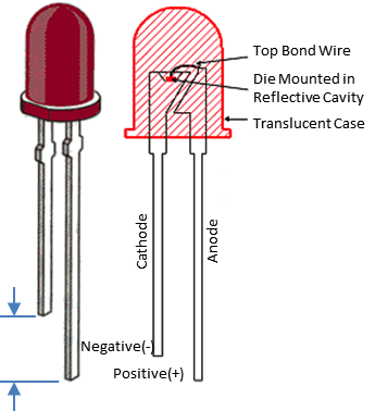
Looking at the image on the left we can see that the LED has two connections. The devices electrical characteristic is polarity sensitive, so it is important to learn how to recognise the connection types and to ensure that they are connected to the correct polarity in your circuit. When supplied as new components the length of the connecting wires are different with the positive ‘anode’ connection being longer than the negative ‘cathode’ connection. However if the leads have been cropped to the same length you can still determine the correct polarity by holding the device up to the light, such that you can see through its translucent body, as the negative cathode connection is made to the larger piece of internal material. |
||||||||||||||
 |
||||||||||||||
|
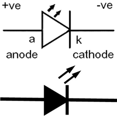
Two electrical symbols for an LED are shown on the right, with the lower simplified filled in image being the more common symbol in practise, as the connection types are interpreted from the shape of the symbol itself. When a voltage is applied to the device, sufficient to cause current conduction, the current is said to flow through the device from its anode to its cathode, as implied by its arrow shaped symbol. |
||||||||||||||
 |
||||||||||||||
|
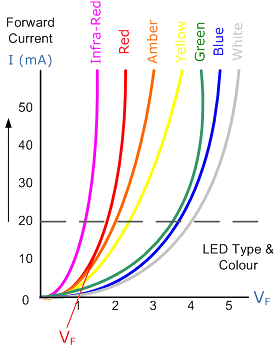
If we now look at the typical electrical characteristics of different coloured LED devices, in which the forward voltage across the device is measured on the horizontal axis and the vertical axis represents the current through the device, as seen in the image on the left. At a typical current of 20 mA it can be seen that the forward voltage across a white LED is four times that of an infra-red LED, and that the forward voltage across a red LED is less than half that of a green LED. These differences need to be taken into account when calculating the value of the series resistor to be selected to control and limit the forward current, particularly when different coloured LED’s are being used in the same project. As a rule of thumb a current as small as 10 mA is sufficient to light an LED and at 20 mA the device will appear to be quite bright to the naked eye. Typically we will derive this current from the 5 volt supply on the Arduino pcb and drive each LED from an output pin. But if you need to drive several LED’s from the same output, this would be done via an external transistor, and you may choose to use a higher supply voltage if the LED’s are to be connected in series with one another. |
||||||||||||||
 |
||||||||||||||
|
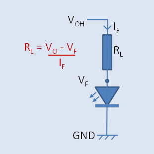
If we want the LED to light when driven from an output in the HIGH state, we would connect the LED and series resistor as shown on the right. In your circuit the series resistor RL can be placed before the LED as shown or after it, it makes no difference to the calculation. If the drive current is small, say 5 mA then we can ignore the voltage drop across the output stage of the micro controller and assume VOH = 5v. For a red LED the forward voltage from the graph above would be 1.2 v and the calculation returns a resistance value of 760 ohms. But if we want the LED to be quite bright, a current of 20 mA can be chosen, which is the limit of the micro controller output stage, at which point it will drop 0.5v and the LED VF would be 1.5 v, so the calculation returns a value of 150 ohms. |
||||||||||||||
 |
||||||||||||||
|
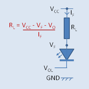
If we want the LED to light when driven from an output in the LOW state, we would connect the LED and series resistor as shown on the left. In this case VCC is assumed to be 5 v. Using the same examples above, if the drive current is small, say 5 mA then we can ignore the voltage drop across the output stage of the micro controller and assume VOL = 0 v. For a red LED the forward voltage from the graph above would be 1.2 v and the calculation returns a resistance value of 760 ohms. But if we want the LED to be quite bright, a current of 20 mA can be chosen, which is the limit of the micro controller output stage, at which point it will drop 0.5v and the LED VF would be 1.5 v, so the calculation returns a value of 150 ohms. As a rule of thumb, using a 220 ohm resistor in series with your LED’s in either configuration will give you lamps that are quite bright and noticeable, and you will not overload the Arduino output pin. |
||||||||||||||
 |
||||||||||||||
|
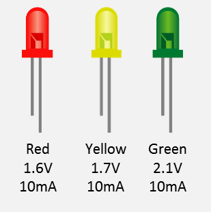
Using the characteristic curves and a nominal current of 10 mA we see typical values for forward voltage drop VF in the image to the right. At this current the Arduino output stage would typical drop 0.2 volts, so we can calculate resistor values for each LED colour as follows: Red = 320 ohms You can connect LED’s in series if you wish to drive two or more at the same time, but given the respective voltage drops only two can be used with a 5 volt rail if they are yellow or green, and three if they are red. You simply add the VF values together in the above calculation. If you want to drive more that three then you would connect them in either a parallel or series configuration and use a transistor to act as the switching device. |
||||||||||||||