
- Project
HexBot2
Here I’ve revisited one of my earlier projects to include a wide range of improvements. This 3-D printed bot is based on an ESP32 microcontroller, which has built in 2.4GHz Wi-Fi and performs much quicker than the Arduino MEGA used in the original design. Watch the video below to see how well it performs, both as a stand-alone autonomous robot as well as being controlled from a Wii Nunchuk via Wi-Fi.
 |
|||||
| Project Overview Click on the image to the right to see the robot being put through its paces. The battery monitoring system gives a good indication of battery capacity and remaining life. |
|||||
|
|
|||||
| The design was created using a 3-D modeller and printer, to ensure that the assembly goes together with ease. And a set of tools can be printed to aid with the essential calibration process, that must be followed to get the servos working exactly as expected. Digital servo motors are used throughout, to ensure best performance and avoid any unexpected movement when power is applied; as normally seen with analogue servos. Digital servos also have metal body shells, which helps to keep them cool when working hard. The body is essentially made in tow halves, which are then screwed together. The idea behind this is that the lower body, attached to the legs, could be associated with a different style of upper body, known as the microplate. So you could redesign the body plate if desired. |
|||||
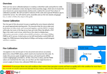
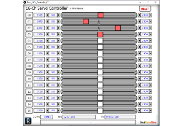
In order to accurately calibrate each servo, the code in the HexBot2 enables it to be linked to a Windows based app, over the USB serial link. I developed this Windows app in ‘Processing’ and you can download the Java executable file from a link below.
With a connection established to the HexBot2, you can simply select a target servo of your choice by clicking on a button in the app, and then change its PWM values by adjusting a slider with the mouse. This enables you to determine minimum and maximum PWM values, which are entered into the ESP32 code in the IDE. Essentially we are mapping PWM values to know angles in degrees, such that the robot code can then work in degree angles using a simple mapping process. This approach is also very useful, should you ever need to change a servo due to failure. You simply re-calibrate it to the reference angles, and nothing more is needed.
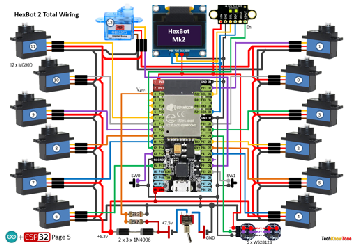
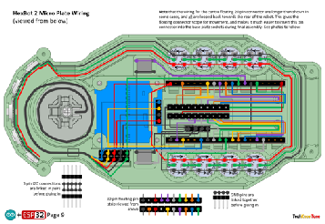
The circuit diagram is shown here on the left, with the ESP32 connected to the 13 servo motors, with 6v power being fed to the servos from a diode voltage dropping circuit. Servos will normally operate between 4.8v and 6v, but they work much better at the higher voltage. Note that this circuit assumes an input voltage of 7.5v from a power plug or 7.4v from a rechargeable battery pack. If you want to use a higher voltage you will need to modify this circuitry to suit, otherwise you could damage your servos
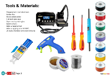
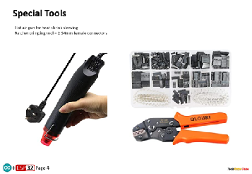
In construction I use wire wrap technology to make the process easier and more reliable. There is however an initial outlay in buying the wrapping tool and spools of wire. As there are a significant number of cables coming from the 12 leg servos, for this project I invested in a ratchet crimping tool, so that I could crop the servo leads to the appropriate length. This worked well in practise and produces a much tidier design.
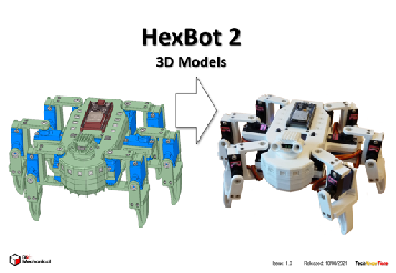
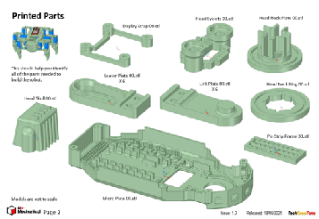
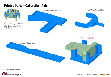
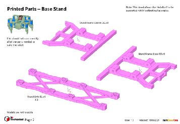
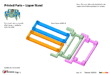
All of the 3-D models are provided as STL files, zipped together into one file. They can therefore be used with a slicing application of your choice, to create the g-files for use with a 3-D printer. For my project I used PrusaSlicer, which is a free download from the internet. I’ve also included a angle gauges and stands, used during the calibration process, and an assembly dressing aid, which helps you get perfect right angles on leg joint parts, using a flat needle file.
The project is meant to be built in two parts, one being the HexBot2 robot and the other being the Wii wireless control box. You will need to download models and instructions for that project from this page here. Whilst the HexBot2 does operate in several stand-alone modes, without doubt the use of the Wii Nunchuk and wireless link are great additions to this project. The wireless project is also used with several other projects and is likely to be needed for others in the future.
Design Files
The following files can be downloaded to help you complete this project. Each has a hyper-link and an associated description. Depending on how your web browser is configured the links will either open the files directly into the browser or offer them as downloads.
Circuit Diagram - a detailed pdf of what is seen in the view above. Use it as a step by step guide to wiring up your project. Updated: 08/12/2025.
Parts list - the things you will need and budget prices, Wii Nunchuk WiFi controller not included; see separate project.
3-D Models - a zip file containing all of the STL files, which you can use with a slicer application.
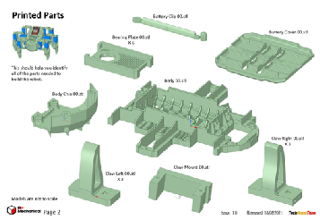
3-D Parts - a pdf file which identifies the 3-D parts, their critical features and how to prepare them for assembly
Software - the all important code, .ino files for HexBot2 and WiFi transceiver, plus a ‘Processing’ application. Updated: vR2. 2024/07/14.
Calibration - shows the critical angles you need to determine and enter into your code to calibrate your servo motors. Updated: 08/12/2025.
Demo Functions - a pdf explaining the functions available with buttons and when using a Wii Classic controller.
Libraries
This project relies on the use of ten libraries, <Arduino.h>, <HardwareSerial.h>, <ESP32Servo.h>, <Wire.h>, "SSD1306Wire.h", <FastLED.h>, "SparkFun_VL53L1X.h”,<esp_now.h>, <WiFi.h>, <EEPROM.h> which need to be included in the IDE set-up, in order for the .ino code to compile correctly. If you haven’t used an ESP32 before with the Arduino IDE, then you will need to install the board libraries too. There are several articles on the web that explain this process.
Design Notes:
The following notes will help you understand how the files in this project work or can be used in principle. Each note has a bold heading for quick reference and they are listed in alphabetical order.
.ino File - the software .zip file contains three folders: HexBot2, Proc_16ch_Controller_06, and Wii_WEMOS_Transceiver_O1, which in turn contains several files. These are all to be extracted and retained within the same folders, of those named. If you are wondering why there are several .ino files, it is because I use the tabbed interface within the Arduino IDE, and for each tab there is a corresponding .ino file. The PWM controller app is a compiled Java version, which will run without installation, once decompressed from the zip file into a normal folder.
3-D Models - this design is based on the use of 2x10 mm steel countersink screws. The pdf files provided should give you sufficient information to identify the parts and indicates the quantity of each to be printed.
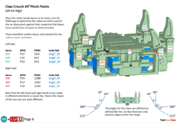
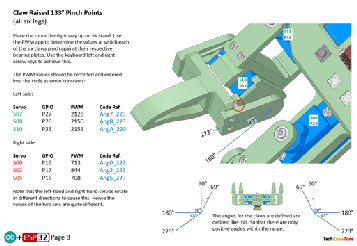
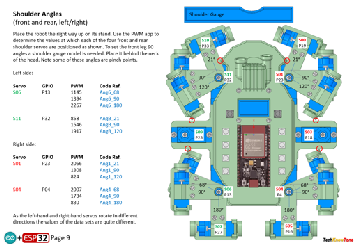
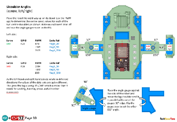
Calibration - It is essential that you undertake a calibration exercise, in order to enter the correct values into your .ino file, as servo values can vary widely. The more accurately you perform this important process, the better the walking performance of the robot. To make the process simpler I have included some additional 3D parts in the form of angle gauges.
Serial Port - is used in this design convey readings and commands to the HexBot2, and for general debugging purposes. Being able to see the servo values being applied to each servo is very useful and essential to calibration. If you also build the WiFi Transceiver project you will be able to connect that unit to your PC via USB and communicate wirelessly with the HexBot2.
STL Model Files - use these with your favourite slicer application. In the 3D Parts pdf document I have indicated the size of pilot holes needed for the screws..
Need more?
If you feel that I haven’t included enough information to allow you to tackle a project of this type then send me an email explaining what you need. Or if you just want to give me some general feedback on this site, or to suggest projects what I might include which would be interesting to you, I’d be pleased to hear from you.
Page updated: 08/12/2025