
- Project
Wii WEMOS D1 Transceiver
As the Espressif ESP8266 and ESP32 microcontrollers have built-in wireless capability, it made sense to develop a new transceiver that would take advantage of this ESP-NOW communications technology. So this wireless unit is needed for projects like PixyBot2. There are two versions here, one using a PP3 battery and the other using 19650 Lithium batteries.
Project Overview
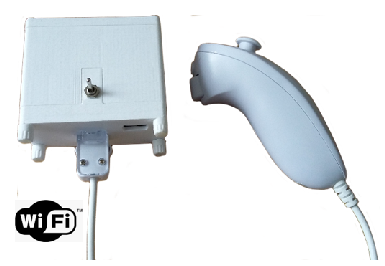
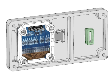
Like its predecessor this unit uses a rechargeable PP3 9v battery, but now contains a WEMOS D1 ESP8266 microcontroller board and a 64 x 128 OLED display. It’s role is to convey demands from either a Wii Nunchuk or Classic controller, as well as act as a transparent link between your project and an application running on a PC.
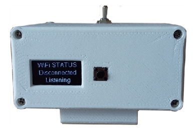
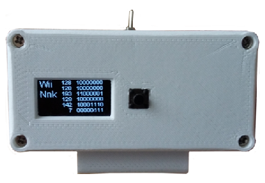
The unit detects which type of Wii controller is connected and conveys that in its message structure to the remote robot. Once connected the robot type is presented on the OLED display and you can examine the values being sent from the controller in real time. Having a display means that I could swap the previous LED flashing for one of presenting battery voltage data and giving a prediction as to battery life, based on its discharge characteristic.
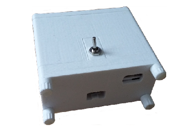
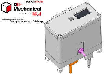
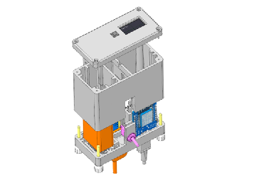
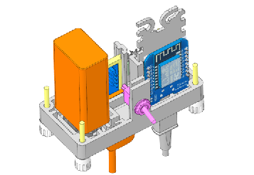
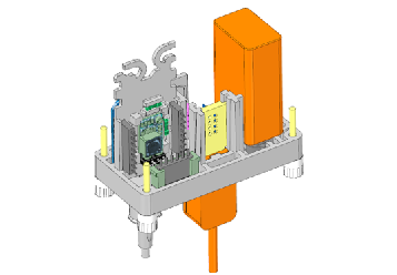
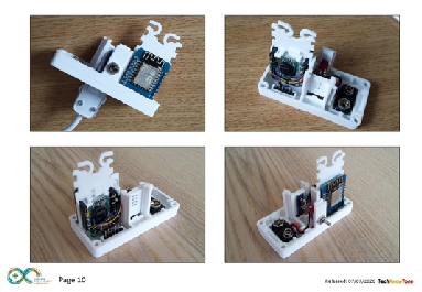
The 3-D design was produced using Design Spark Mechanical, based on an assembly of all of the components, including models of the electronic components, like the WEMOS D1, the PP3 battery, voltage regulator, switch etc.
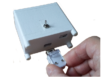
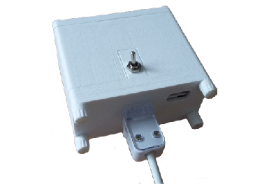
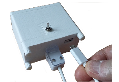
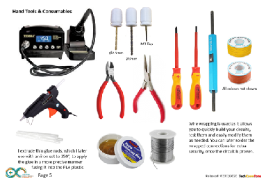
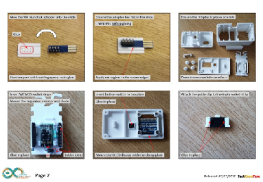
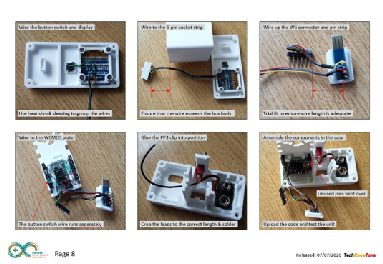
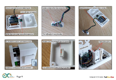
The great thing about 3-D modelling and printing is the accuracy of the component produced, and the way in which the design simply goes together. Once you have printed the parts, all you need to do prior to wiring and assembly is to apply a 3mm thread to some of the holes using an M3 tap. You will also need to use some epoxy resin quick set glue to position the Wii adapter in the slide, and some hot melt glue to hold the items in position.
All of the step by step instructions are contained in the wiring diagrams pdf document.
The build instructions advise you on what hand tools you are likely to need to complete the construction of this project. The vast majority of the wiring was done using a method known as wire wrapping. Whilst the initial cost of the wrapping tool and coloured wire spools will be a small sum, use of this technique makes the detailed wiring much simpler to perform. It has the added benefit of being able to test the design in its wrapped form, and should you find an error it is relatively easy to unwind the wiring and fix the problem, before finally soldering the joints.
This is an old technique that was well proven in the early days of developing Apple computers; when the cost of producing a large printed circuit board was quite prohibitive. Since then of course, the cost of producing pcb’s has fallen significantly and is now well within the grasp of the hobbyist. Once the wiring is proven I still solder the joints for added reliability, but that is not absolutely necessary.
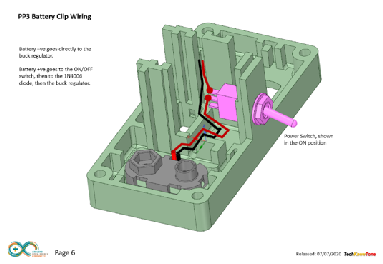
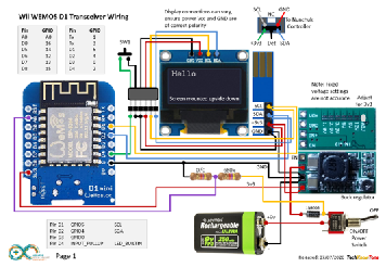
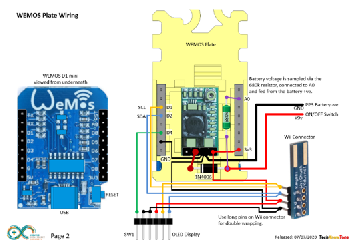
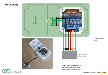
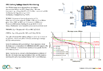
The circuit diagram is shown here on the left, with the WEMOS D1 connected to the OLED display and small Wii adapter pcb. The battery voltage is sourced via the ON/OFF toggle switch, a diode and a 5v voltage regulator. The diode has been added to prevent accidental damage to the electronics, should the switch be ON and the battery is applied the wrong way round to its connector. The battery voltage is also measure by the micro, via a potential divider circuit, to indicate power loss to the user. I have included a discharge curve and an explanation of how the limits in the code are derived, which you can set accurately with a multimeter if you like.
The USB connector on the WEMOS D1 is used for serial communications once a link is established. The code indicates the presence of a Wii controller, its type and the data being received from it in numerical and binary format. I have found the ESP-NOW wireless protocol to be more reliable for telemetry, than the simple serial transceivers used in previous projects.
Design Files
The following files can be downloaded to help you complete this project. Each has a hyper-link and an associated description. Depending on how your web browser is configured the links will either open the files directly into the browser or offer them as downloads.
Here are the files for the original PP3 version:
Circuit Diagram - drawings of what is seen in the view above, as a guide to wiring up your project.
Parts list - the things you will need and budget prices.
3-D Models - a zip file containing all of the STL files, which you can use with a slicer application.
3-D Parts - a pdf file which identifies the 3-D part STL file references you will need to print.
Software Code - the all important Arduino .ino file which runs the project and ‘Processing’ application. See comments below on coding.
Wii Nunchuk interface - a useful data sheet showing electrical connections and I2C register assignments.
Here are the files for the 18650 battery version:
Circuit Diagrams - circuit schematics and assembly photos. Updated: 08/12/2025.
Parts List - modified to include 18650 batteries.
3-D Models - a zip file containing all of the STL files, for your slicer and 3D printer.
3-D Parts - a pdf file which identifies the 3-D parts.
Libraries
This project relies on the use of several library components Arduino.h, EEPROM.h, Wire.h, ESP8266WiFi.h, espnow.h, and SSD1306Wire.h, which all need to be included in the Arduino IDE set-up.
Design Notes:
The following notes will help you understand how the files in this project work or can be used in principle. Each note has a bold heading for quick reference and they are listed in alphabetical order.
.ino File - when you download this file remember to place it in a folder with the same name, otherwise the Arduino IDE will not load it and display an error message.
3-D Models - this design is based on the use of 3mm nylon countersink screws. The models have 2.5mm pilot holes which need to be threaded with a M3 tap to secure the box body to the lid.
STL Model Files - all models are designed to be printed on a 3-D printer with a .4mm nozzle. If you use a printer with a finer nozzle, say 0.3mm, then this may result in the height of the components being slightly less than intended, but I would still expected them to work..
Need more?
If you feel that I haven’t included enough information to allow you to tackle a project of this type then send me an email explaining what you need. Or if you just want to give me some general feedback on this site, or to suggest projects what I might include which would be interesting to you, I’d be pleased to hear from you.
Page updated: 08/12/2025