
- Project
PIX Lamp(ESP32)
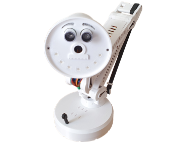
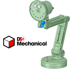
An angle poise lamp, styled on PIXAR, incorporating an AI camera, was the focus of this project. Here you will see how I used a HuskyLens AI camera, in conjunction with an ESP32 microcontroller, to make a remarkable face tracking robot. This will be great for demonstrating to students how face recognition can be used, in what is a relatively low cost project. Given the capacity of an ESP32, there is still plenty of scope to add features of your own, or adopt the code in another project.
Project Overview
This project harnesses the AI capabilities of the HuskyLens camera, by controlling it using an ESP32 microcontroller, in the form of an angle poise lamp, styled on PIXAR. Using the I2C serial interface, the code in the ESP32 is able to gather ID and co-ordinate data from the camera, to enable it to track faces and objects in real time. It has been developed as a demonstrator for school STEM students, who have an interest in robotics and coding.
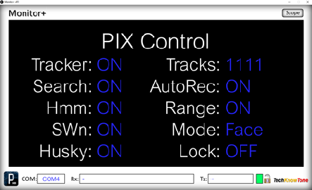
Whilst the PIX lamp can be operated in standalone mode; the demonstration is greatly enhanced by linking it to a PC, using a Wi-Fi module. As this allows the ESP32 to present screens of data using a Windows app, known as Monitor+. Watch the video on the right, to learn more about this interesting project.

|
|
||||
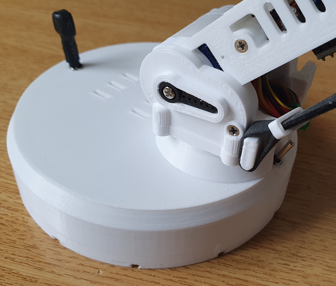
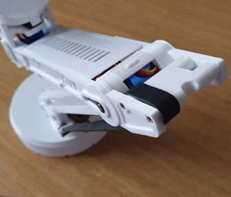
| The Tower Pro MG92B servos, used in this project, provide a lot of torque, for their small size; and it’s needed in this type of design. Despite their strength, they would not be unable to raise the lamp, if it was not for the elastic band; which acts as a lifting spring. Taking most of the load off the upper arm, this keeps the servo operating within safe limits. But you do have to be mindful of loading and toppling limits, when moving the joints; which use ball bearing races to reduce friction. There are five servos in total, one in the base, one in each arm joint, and two as pan and tilt servos for the lamp. As part of the build process, you will need to calibrate these servos, to determine their PWM values for critical angles. This then allows the code to consider all movements as angles, not PWM, and ensures that the robot can be produced with a different set of servos. A calibration procedure has been written, to walk you through this important task. All of the plastic parts are created from 3-D models, for which STL files have been provided.. |
||||
|
|
||||
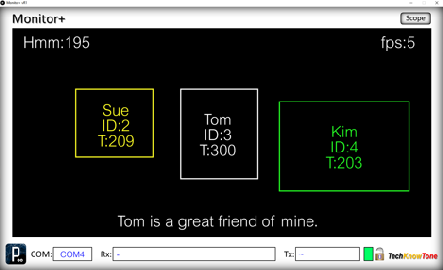
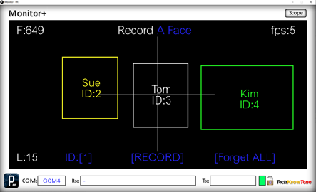
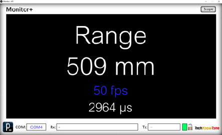
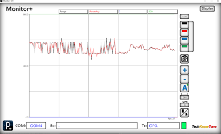
| This robot can be used in conjunction with a Windows PC, on which you would run the provided Monitor+ app. This app was written originally to show what is actually being displayed on a 128x64 OLED display, but can also be used without the need for display hardware, This all works over Wi-Fi, and the screens presented are all generated by the code in the ESP32, and accessed by simply clicking on the displays screen. The Monitor+ app can also be switched into ‘Scope’ mode, in which it requests data from the micro, and presents it as waveforms, or numerical lists. In this project I’ve extended the scope of the Monitor+ app, to display more colours, a wider range of front sizes, and auto-repeat on mouse clicks, when adjusting values. The use of the SHIFT-key is also recognised, and sent to the micro. This is great for adjusting things like servo values. |
||||


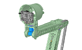
The circuit diagram shows the wiring of the PIX lamp, in which the physical circuitry is distributed around the body. This is partially to distribute weight, but also to provide short power wires to the HuskyLens camera; which does draw significant currents. For development purposes the robot can be power from an external supply; which is useful if you want to monitor the currents flowing into the servos.
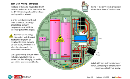
The 18650 battery voltage is converted to 3.4v in a buck regulator, for efficiency; and the battery voltage is monitored by the ESP32, and displayed in the Monitor+ app, when connected. In addition to the power ON/OFF switch there is a large toggle switch at the front on the base, and a push button switch on the rear of the lower arm. These control the primary behaviour of PIX; but there are more features to be accessed via the Monitor+ app; such as setting flags to control face tracking, etc.
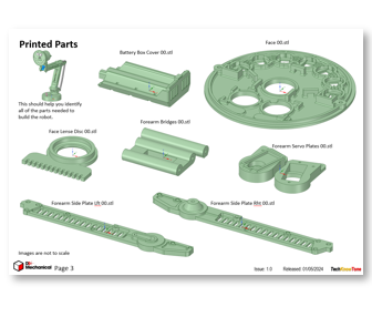
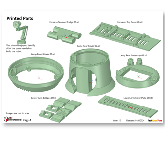
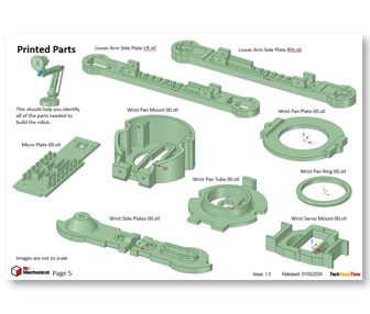
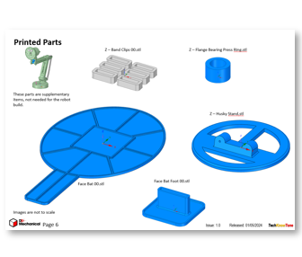
All of the 3-D models are provided as STL files, zipped together into one file. They can therefore be used with a slicing application of your choice, to create the g-code files for use with a 3-D printer. For my project I used PrusaSlicer, which is a great app and a free download from the internet. Models for assembly aids, and testing are also included.
I’ve also provided a pdf file showing you the names of each component and the quantities you need to print of each. The design is essentially held together using 2 x 10 mm self-tapping dolls house screws, making it strong and rigid, whilst still being able to take it apart, should you need to changed a component. The lower arm, contains the ESP32 micro plate; and the rear of the lamp has a window, through which the HuskyLens screen can be viewed
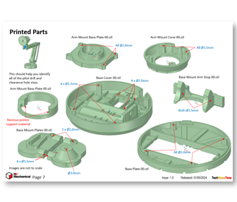
I’ve used a simple design for the face of PIX, but a more complex one could be added, if you like. The 3-D parts document details the pilot hole sizes needed for each part, and also helps you to identify all of the printed components. The modelling assumes a 0.4mm nozzle size on the printer.

Design Files
The following files can be downloaded to help you complete this project. Each has a hyper-link and an associated description. Depending on how your web browser is configured the links will either open the files directly into the browser or offer them as downloads. Note that these documents only refer to the PIX lamp robot. You are likely to want to make the Wi-Fi D1 Transceiver project as well, in order to use Monitor+ app with it.
Circuit Diagrams- drawings of what is seen in the views above. Use it as a guide to wiring up your project. Updated: 08/12/2025.
Parts list - the things you will need to build this project. You will also need to make the WiFi transciever project, found here..
3-D Models - a zip file containing all of the STL files, which you can use with a slicer application.
3-D Parts - a pdf file which identifies the 3-D parts, pilot drill sizes, and the quantities of each you will need to 3-D print.
Software Code - the all important code files, which runs the project, and ‘Processing’ apps. See comments below on coding. Updated: vR1, 15/08/2024.
Calibration Record - explains the things you will need to accomplish to get the Uni-Bot self-balancing. Updated: 08/12/2025.
Demo Functions - a pdf outlining how you control the PIX lamp robot.
Libraries
This project relies on the use of six libraries, <Arduino.h>, <HardwareSerial.h>, <FastLED.h>, <esp_now.h>, <WiFi.h>, “HUSKYLENS.h”, <ESP32Servo.h>,in the PIX lamp code, which may need to be included in your version of the Arduino IDE set-up.The RGB LEDs are controlled using the FastLED functions and the Wi-Fi link relies on the use of the ESP-NOW protocol. Note that Tabs have been used within the IDE, to simplify editing, so there is a separate .ino file for each of the six tabs. All of which must be included in the PIXAR_Lamp_R0 folder,
Design Notes:
The following notes will help you understand how the files in this project work or can be used in principle. Each note has a bold heading for quick reference and they are listed in alphabetical order.
Software Code - when you download this .zip file, and unzip it; the folder extracted contains several folders as follows:
PIX_Lamp_R0 - a folder containing the .ino files, for the ESP32. Note multiple files for the tabbed interface.
Proc_16Ch_Controller_x32 - a 16-channel controller app, compiled for older x32-bit PCs.
Proc_16Ch_Controller_x64 - a 16-channel controller app, compiled for x63-bit PCs.
Proc_MonitorPlus_x32 - a display monitor app, compiled for older x32-bit PCs.
Proc_MonitorPlus_x64 - a display monitor app, compiled for x64-bit PCs.
Note that the .ino folder contains several files. This is because I use the tabbed interface of the Arduino IDE, which saves a separate .ino file for each tab. You need all of these files in the project folder for the code to compile correctly.
3-D Models - this design is based on the use of 2x10mm dolls house self-tapping screws. The models have 1.5 mm pilot holes for the self-tapping screws. The pdf file helps you identify all of the parts, and indicates pilot hole sizes.
Calibration Record - It is essential that you undertake calibration tasks, in order to enter the correct values into your .ino file. Otherwise the robot will not function correctly and could even result in damage and over-heating of the servo motors.
STL Model Files - all models are designed to be printed on a 3-D printer with a 0.4 mm nozzle, with slicer layer heights of 0.3 mm.
Need more?
If you feel that I haven’t included enough information to allow you to tackle a project of this type then send me an email explaining what you need. Or if you just want to give me some general feedback on this site, or to suggest projects what I might include which would be interesting to you, I’d be pleased to hear from you.
Page updated: 08/12/2025