
- Project
Uni-Bot (ESP32)
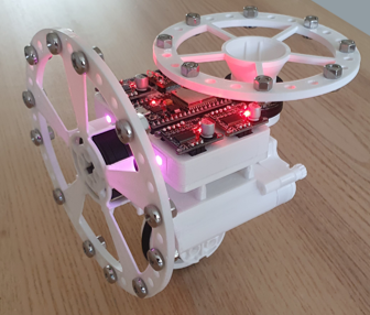
A self-balancing unicycle robot is a challenging and interesting project, that can offer a great learning experience from both a coding and practical perspective. Here I have made one using three BLDC motors and two reaction wheels, which can be controlled using a Wii Nunchuk controller over Wi-Fi. ESP32 microcontrollers are great for projects like this.
Project Overview
This robot uses an MPU6050 3-axis sensor, plus three BLDC gimbal motors, to achieve self-balance, forward and reverse motion, and turning. The motors are controlled electronically using SimpleFOC mini driver boards, and PID controller code within the ESP32 micro.; which also manages the Wi-Fi control link. DC power is taken from 3 x 18650 Lithium batteries, and two RGB LEDs provide visual status tell-backs to the user.
Over the Wi-Fi link a PC based app can easily be connected to display a large array of information screens, which allow for variables to be adjusted with the click of a mouse button. This makes tuning the robots PID controllers relatively easy, and also displays data in the form of waveforms. The existing options can be easily tailored and extended by you. Check out the video link opposite.

|
|
||||
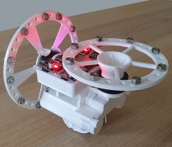
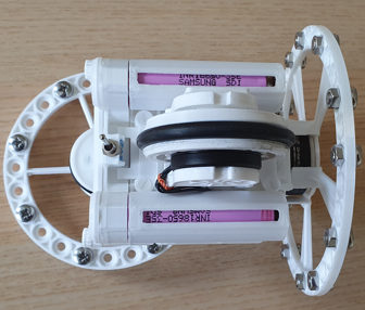
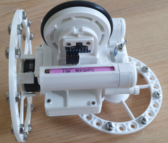
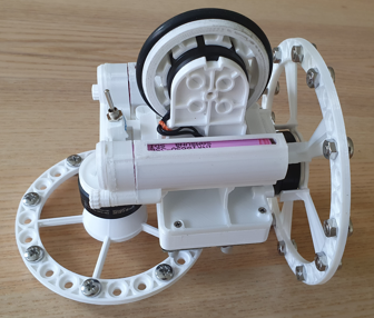
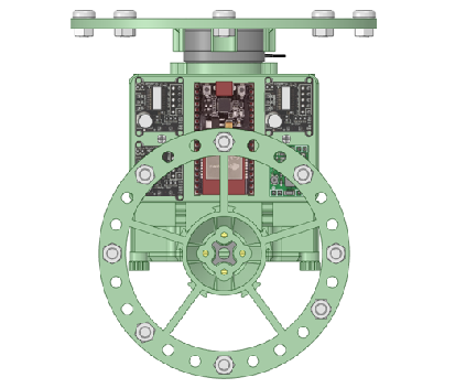
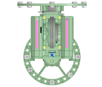
| To reduce the parts count and cost, this design uses the SimpleFOC mini BLDC motor driver boards, which don’t included current sensing resistors, and controls them in open loop velocity mode, without the use of rotary encoders. This means that the code needs to carefully control the PWM voltages applied to the motors, to prevent them over-heating, and ensure that the rotating magnetic fields within the motors do not exceed the commutation rate possible, for the applied PWM voltages. This was achieved by building into the code test routines, that allowed for empirical evaluation of the motors, for a given size of reaction wheel and weight distribution. As reaction wheels only produce a turning force when accelerating, there is a limit as to how fast the motors can be spun, and a max. rate at which they can be accelerated. Also the weight bearing wheel is made from a single fat o-ring, with a circular cross sectional area, so there is no flat surface on which the Uni-Bot might naturally balance. Like a broad flat tyre or multiple o-ring solution, which some designs rely on. So there are no button switches or displays in this design. |
||||
|
|
||||
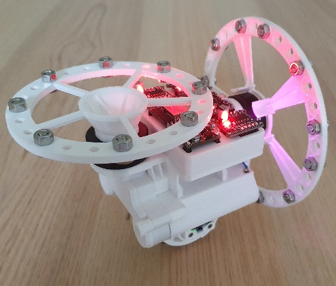
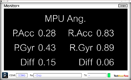
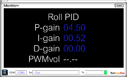
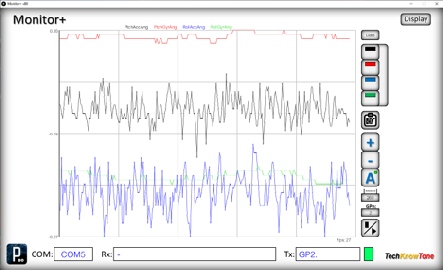
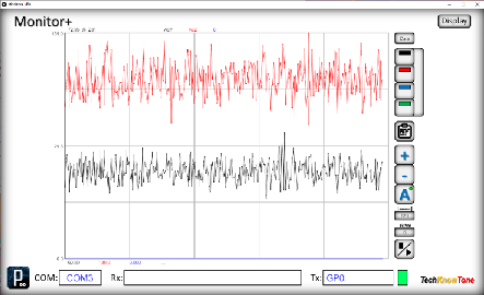
| This robot is intended to be used in conjunction with a laptop PC, on which you would run the provided Monitor+ app. This app was written originally to show what is actually being displayed on a 128x64 OLED display, but can be used without the need for display hardware, In this project I have further enhanced the app so that it can display coloured text, and the user can click within the app window to switch between displays and even modify the value of variables, to aid PID tuning. The code in the ESP32 micro creates each display, and they can easily be modified or extended. The Monitor+ app can also be switched into ‘Scope’ mode, in which it requests data from the micro and presents the data as waveforms, or numerical lists. You can even pause the trace and move the mouse pointer within it, to see what the trace values are at a given point. Up to four simultaneous traces of variables are supported. |
||||
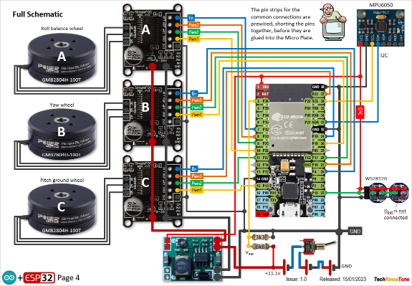
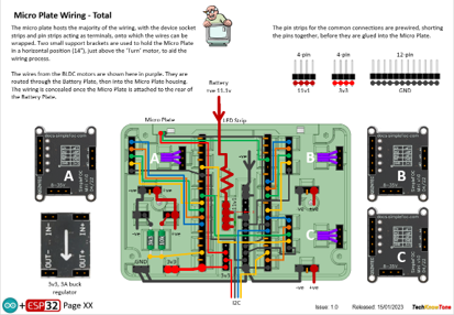
The circuit diagram is shown here on the left, with the ESP32 being supplied from a 3v3 regulator and connected to the three SimpleFOC mini drivers, the MPU6050 3-axis sensor and the two RGB LEDs. Most of the wiring is retained with the Micro case, with the ESP32 micro, the three motor drivers and regulator being plugged in from the top face.
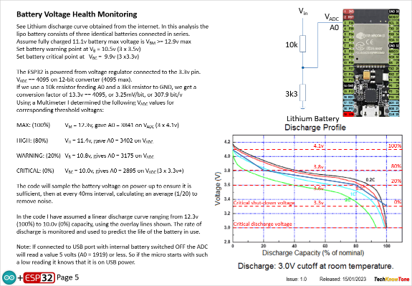
The code in the micro is able to sample the battery voltage and use that, over time, to vary the strength of the PWM signals being applied to the BLDC motors. This is important as the motors can run quite hot, or fail to commutate if not controlled correctly.
The orientation of the Uni-Bot, obtained from the MPU6050, is used to trigger the Uni-Bot into self-balancing mode; whilst the RGB LEDs provide useful tell backs in the form of colour changes. There are no rotation sensors used in this design; with the motors being driven in open loop velocity mode.
All of the 3-D models are provided as STL files, zipped together into one file. They can therefore be used with a slicing application of your choice, to create the g-code files for use with a 3-D printer. For my project I used PrusaSlicer, which is a great app and a free download from the internet. Models for assembly aids, and testing are also included.
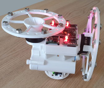
I’ve also provided a pdf file showing you the names of each component and the quantities you need to print of each. The design is essentially held together using 2 x 10 mm self-tapping dolls house screws, making it strong and rigid, whilst still being able to take it apart should you need to changed a component. The reaction wheels are attached to the BLDC motors using 3mm nylon screws, and the weights are made up of M5 bolts and nuts.
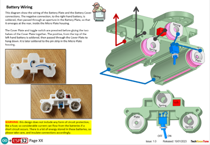
The battery cover is held in position with two M3 x 30 mm nylon screws, and has an integral blade battery connection; allowing it to be completely withdrawn from the Uni-Bot for simple battery replacement. The fat o-ring, which forms the tyre, is circulate in cross-section, so this robot is not reliant on a flat profiled tyre to aid balancing, like some are..
Design Files
The following files can be downloaded to help you complete this project. Each has a hyper-link and an associated description. Depending on how your web browser is configured the links will either open the files directly into the browser or offer them as downloads.
Circuit Diagrams- drawings of what is seen in the views above. Use it as a guide to wiring up your project. Updated: 08/12/2025.
Parts list - the things you will need to build this project. You will also need to make the WiFi transciever project, found here..
3-D Models - a zip file containing all of the STL files, which you can use with a slicer application.
3-D Parts - a pdf file which identifies the 3-D parts, pilot drill sizes, and the quantities of each you will need to 3-D print.
Software Code - the all important .ino code file, which runs the project, and a ‘Processing’ application. See comments below on coding.
Calibration Record - explains the things you will need to accomplish to get the Uni-Bot self-balancing. Updated: 08/12/2025.
Demo Functions - a pdf outlining how you control the Uni-Bot robot.
Libraries
This project relies on the use of six libraries, <Arduino.h>, <Wire.h>, <SimpleFOC.h>, <FastLED.h>, <esp_now.h>, <WiFi.h> which may need to be included in your version of the Arduino IDE set-up.The RGB LEDs are controlled using the FastLED functions and the Wi-Fi link relies on the use of the ESP-NOW protocol. Note that Tabs have been used within the IDE, to simplify editing, so there is a separate .ino file for each of the six tabs. All of which must be included in the Uni_Bot_R0 folder,
Design Notes:
The following notes will help you understand how the files in this project work or can be used in principle. Each note has a bold heading for quick reference and they are listed in alphabetical order.
.ino File - when you download this .zip file, and unzip it; the code project folder contains several .ino files. This is because I use the tabbed interface of the IDE, which saves a separate .ino file for each tab. You need all of these files in the project folder for the code to compile correctly.
3-D Models - this design is based on the use of 2x10mm dolls house self-tapping screws. The models have 1.5 mm pilot holes for the self-tapping screws. The pdf file helps you identify all of the parts, and indicates pilot hole sizes.
Calibration Record - It is essential that you undertake calibration tasks, in order to enter the correct values into your .ino file. Otherwise the robot will not function correctly and could even result in damage and over-heating of the BLDC motors.
STL Model Files - all models are designed to be printed on a 3-D printer with a 0.4 mm nozzle, with slicer layer heights of 0.3 mm.
Need more?
If you feel that I haven’t included enough information to allow you to tackle a project of this type then send me an email explaining what you need. Or if you just want to give me some general feedback on this site, or to suggest projects what I might include which would be interesting to you, I’d be pleased to hear from you.
Page updated: 08/12/2025