
- Project
Reach Robot
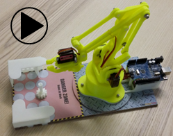
Having access to a 3-D printer greatly extends the range of projects you can tackle. Here I’ve adapted a design for a reach robot, using four miniature servos and an Arduino UNO to create a machine which moves objects around a simple workplace.
 |
||||||
| Project Overview On power-up the code goes into a safe mode after a few seconds, but during that initial wait period it reads and writes data to the EEPROM memory. This enables me to enter one of three modes simply by operating the RESET button in a specific way, saving on the need for additional switches. |
||||||
|
||||||
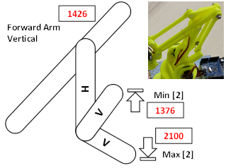
| The design of the mechanical linkages in the reach movement work in such a way that the movement range of the arm, that raises and lowers the head, needs to be constrained depending on the position of the vertical arm, otherwise lock-up would occur. So this limitation is controlled within the code, with the vertical arm angle being set first, then the limits for the raising arm are derived from that. A calibration diagram is included to explain the angles I determined from my robot. As servo tolerances vary quite widely from one part to another, you will need to calibrate these ranges and enter new values into the code to get this to work correctly. This would also apply to my robot should any of the servos fail and need replacing. |
||||||
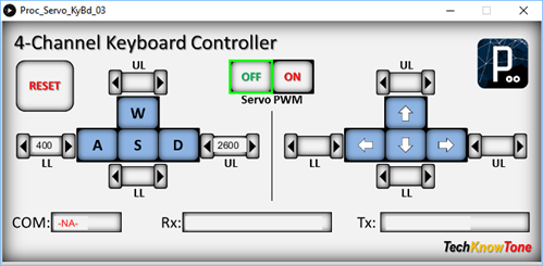
In order to control the robot and determine the correct positions of each servo for moving the gear object around the workspace I developed a Windows PC interface in ‘Processing’. This interface receives keyboard commands from the user and sends them to the UNO, which in turn moves the servos. So you can move the robot using keys and gain feedback on the actual servo values.
The robot then uses code in the form of a ‘movement engine’ which runs through a series of user specified commands, stored in an array. A function is first called to load the command sequence into the array, prior to the movement engine being initiated. Whilst overall this requires mode code, it makes the creation of movement sequences easier to generate and follow. Additional commands could be added to extend the robots scope.
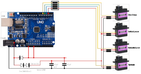
The circuit diagram is shown here on the left, with the Arduino UNO connected to the four servo motors on the right, with 6v power being fed to the servos from a diode voltage dropping circuit. Servos will normally operate between 4.8v and 6v, but they work much better at the higher voltage. Note that this circuit assumes an input voltage of 7.5v from a power plug or 7.2v from a 6 x AA rechargeable battery pack. If you want to use a higher voltage you will need to modify this circuitry to suit, otherwise you could damage your servos
It is also better not to power the servos from the UNO 5v linear regular, as any dip in supply voltage caused by loading a servo could result in the UNO being reset via its internal brown-out circuitry. Connecting one servo that way for test purposes is fine, but I wouldn’t recommend any more.
All of the 3-D models are provided as STL files, zipped together into one file. They can therefore be used with a slicing application of your choice, to create the g-files for use with a 3-D printer. For my project I used Slic3r which is a free download from the internet.
For the corner pieces I chose to use a method of construction in which the part is printed as a relatively flat piece and then folded together like a piece of origami. To maintain the desired shape the seams are effectively welded together using thin pieces of printed plastic welding rods and a soldering iron set to a temperature of 360 degrees. This method proved to be a useful technique and one which I will also use to prevent printed parts from de laminating when put under load.
Design Files
The following files can be downloaded to help you complete this project. Each has a hyper-link and an associated description. Depending on how your web browser is configured the links will either open the files directly into the browser or offer them as downloads.
Circuit Diagram - a drawing of what is seen in the view above, plus veroboard wiring. Use it as a guide to wiring up your project.
Parts list - the things you will need and budget prices.
Physical Templates - drawings produced in Ms PowerPoint. Ensure that they do print at the correct size, if used directly on hardboard.
3-D Models - a zip file containing all of the STL files, which you can use with a slicer application.
3-D Parts - a pdf file which identifies the 3-D parts, their critical features and how to prepare them for assembly
Parts Assembly - a pdf file which shows you how to assemble the printed parts, with screws, washers and nuts
Software Code - the all important Arduino .ino file which runs the project and ‘Processing’ application. See comments below on coding.
Calibration Record - shows the angles you need to determine and enter into your code to calibrate new servo motors.
Programming - shows you how to use the Windows app to create a simple ‘Move’ program for the Reach Robot.
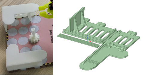
Accessories - a pdf showing extra 3-D models and drawings you can download to create a work area and tasks for your robot.
Wii Classic - a pdf explaining how to add a Wii controller, and associated files you can download from here.
Libraries
This project relies on the use of three libraries, Servo.h, IRremote.h and EEPROM.h, which are included in the IDE set-up. If you don’t adopt the special RESET method I use for selecting the operating mode of the robot, then you won’t need the EEPROM.h library, but it might be in your interest to at least study that code for future use, as it saves the need for additional circuitry.
Design Notes:
The following notes will help you understand how the files in this project work or can be used in principle. Each note has a bold heading for quick reference and they are listed in alphabetical order.
.ino File - when you download this file remember to place it in a folder with the same name, otherwise the Arduino IDE will not load it and display an error message.
3-D Models - this design is based on the use of 3mm nylon countersink screws with niloc nuts as fasteners. This leads to a very clean solution as the length of each screw can be easily trimmed adjacent to the nut using wire cutters.
Calibration Record - It is essential that you undertake a calibration exercised in order to enter the correct values into your .ino file, as servo values can vary widely. Otherwise the mechanical linkages can lock up and servo motors will consume excessive power. Use the keyboard application, or a suitable infra-red remote control to move the robot into the positions indicated.
Serial Port - is used in this design convey readings and commands over the Arduino IDE Serial Monitor, and for general debugging purposes. Being able to see the servo values being applied to each servo is very useful and essential to calibration.
STL Model Files - The forward drive arm has a hidden pocket where the plastic drive leaver from the servo motor is inserted. This is to make the part more printable, and this thin walled pocket can be easily opened up using a hobby knife.
Need more?
If you feel that I haven’t included enough information to allow you to tackle a project of this type then send me an email explaining what you need. Or if you just want to give me some general feedback on this site, or to suggest projects what I might include which would be interesting to you, I’d be pleased to hear from you.