
- Project
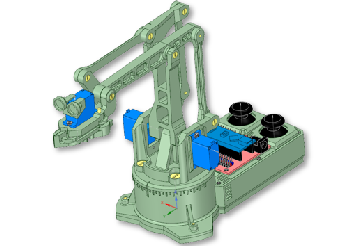
Reach Robot NANO
This robot was designed for Coder Dojo students, who will follow a road map of small projects, developing the skills needed to write code for this robot.. It is based on the use of a NANO expansion shield, and has two joysticks and button switches built in.
Project Overview
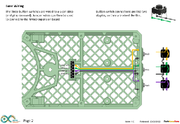
This robot, like my previous Reach Robots, uses four servo motors. One servo for rotation, one for the jaws, and two for the reach movement. You control its movement using two PS2 joysticks and three push button switches at the rear. Mounted inside of the case are two RGB LEDs, used to indicate whether the robot is active or not. All part of the coding challenge.
The robot and case are two separate items, screwed together; allowing you to attach a different more advanced microcontroller if you wish, like an ESP32 used in my Mk1 version. Power is injected via the DC power socket on the NANO expansion shield, normally from a pack of 2x18650 lithium batteries, and the servo motors run off the shields regulated 5 volt rail..

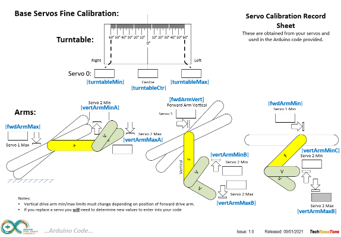
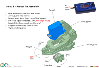
The design of the mechanical linkages in the reach movement work in such a way that the movement range of the arm, that raises and lowers the head, needs to be constrained depending on the position of the vertical arm, otherwise lock-up could occur.
This potentially damaging limitation, is controlled within the code, with the vertical arm angle being set first, then the limits for the raising arm are derived from that. A calibration diagram is included to explain the angles I determined from my robot. As servo tolerances vary quite widely from one part to another, you will need to calibrate these ranges and enter new values into the code to get it to work correctly.
This critical procedure also applies to the robot if any of the servos fail and need replacing.
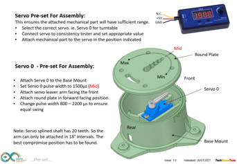
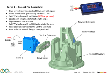
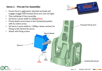
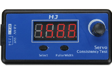
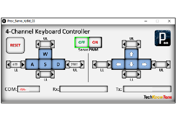
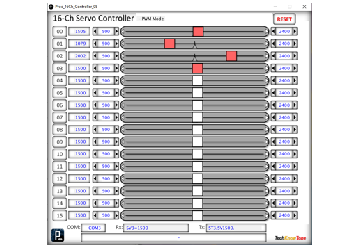
As with most servo projects, you will need to set up the servos when assembling the robot. This is achieved initially using a servo tester for course calibration, and two custom Windows apps, I have provided, created using the ‘Processing’ IDE. The first app receives keyboard commands from the user and sends them to the NANO, which in turn moves the servos. So you can move the robot using keys and gain feedback on the actual servo values. The second provides sliders, which you can use to adjust the servo values, making it quick and easy to find values for specific locations of the robots arm.
The robot also uses code in the form of a ‘movement engine’, which causes the servos to sweep towards target positions, in a number of defined steps, and at a rate specified in the code. This can be used to create a sequence of interesting movements, including the jaws opening and closing.
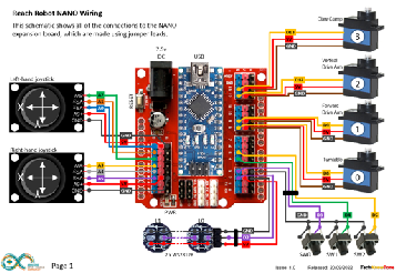
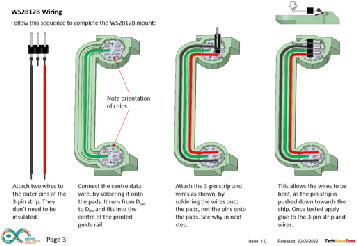
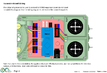
The circuit diagram is shown here on the left, with the Arduino NANO expansion shield connected to the four servo motors on the right, with 5v DC power being fed to the servos from the on-board linear voltage regulator. The two PS2 joysticks plug directly into the analog pins, whilst the WS2812B RGB LEDs and button switches plug into the digital I/O pins. In addition to the X and Y potentiometers, the PS2 joysticks have built-in button switches too.
There are plenty of spare pins for additional items, should you wish to fit them, and the LED strip could easily be extended to many more LEDs if needed. The biggest challenge was getting all of the wiring to fi inside the case, so I have extended the depth of the case by 5mm to make this much easier. You essentially build the robot and control case as two separate items and then screws the two together.
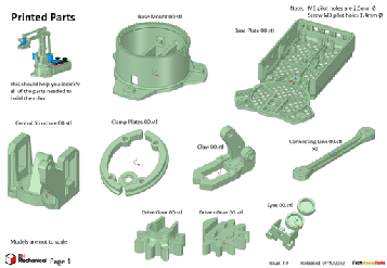
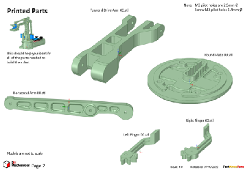
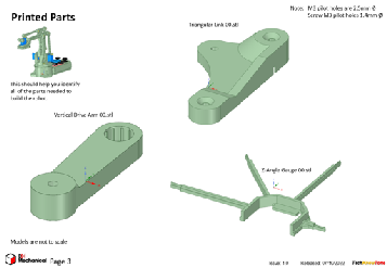
All of the 3-D models are provided as STL files, zipped together into one file. They can therefore be used with a slicing application of your choice, to create the g-files for use with a 3-D printer. For my project I used PrusaSlicer, which is a free download from the internet.
My parts were printed in PLA, using 1.75mm diameter filament, fed through a 0.4mm nozzle. The first layer was printed at 0.3mm height, and subsequent layers at either 0.3 or 0.15mm, depending on the quality of print I desired. The weight of the printed parts was 185g, which means that you could get five sets from a 1kg real of filament.
The design relies on the joystick covers being printed separately, and then glued to the top plate. The rest of the components are held using nylon screws, or 2x10mm self tapping scrrews.
Design Files
The following files can be downloaded to help you complete this project. Each has a hyper-link and an associated description. Depending on how your web browser is configured the links will either open the files directly into the browser or offer them as downloads.
Circuit Diagram - a drawing of what is seen in the view above. Use it as a guide to wiring up your project.
Parts list - the things you will need and budget prices.
3-D Models - a zip file containing all of the STL files, which you can use with a slicer application.
3-D Parts - a pdf file which identifies the 3-D parts, their critical features and how to prepare them for assembly
Parts Assembly - a pdf file which shows you how to assemble the 3D printed parts.
Software Code - the all important Arduino .ino, file which runs the project and two ‘Processing’ applications. See comments below on coding.
Calibration Record - shows the angles you need to determine and enter into your code to calibrate new servo motors.
Libraries
This project relies on the use of two libraries, Servo.h and FastLED.h, which are included in the IDE set-up. If not, you can include them using the library manager. Not surprisingly, Servo.h is used to control the 4 servos in the robot, and the FastLED library is there to control the programmable WS2812B RGB LEDs.
Design Notes:
The following notes will help you understand how the files in this project work or can be used in principle. Each note has a bold heading for quick reference and they are listed in alphabetical order.
.ino File - when you download this file remember to place it in a folder with the same name, otherwise the Arduino IDE will not load it and display an error message.
3-D Models - this design is based on the use of 3mm nylon countersink screws, with M3 threaded components. You will need a long reach tap, for threading the forward arm upper joint. This leads to a very clean solution, as the length of each nylon screw can be easily trimmed using wire cutters.
Calibration Record - It is essential that you undertake a calibration exercised in order to enter the correct values into your .ino file, as servo values can vary widely. Otherwise the mechanical linkages can lock up and servo motors will consume excessive power, and potentially fail. Use the keyboard application provided to move the robot into the positions indicated in the calibration procedure.
Serial Port - is used in this design convey readings and commands over the Arduino IDE Serial Monitor, and for general debugging purposes. Being able to see the servo values being applied to each servo is very useful and essential to calibration.
STL Model Files - The forward drive arm has a hidden pocket where the plastic drive leaver from the servo motor is later inserted. This is to make the part more printable, and this thin walled pocket can be easily opened up, with care, using a hobby knife.
Need more?
If you feel that I haven’t included enough information to allow you to tackle a project of this type then send me an email explaining what you need. Or if you just want to give me some general feedback on this site, or to suggest projects what I might include which would be interesting to you, I’d be pleased to hear from you.
Page updated: 25/10/2022