
- Project
MandalBot - A Self-balancing Robot
As it is now difficult to get parts for my original BalanceBot project (NANO), I've now created an ESP32 based version, in the style of a Mandalorian helmet, using the same stepper motor technology as the original. With ESP-NOW as the more reliable Wi-Fi link, I've also made it much easier to set up and control; giving you options of Wii Nunchuk or Bluetooth controllers. Check out the detail below.
Project Overview
One of my earlier projects was a self-balancing robot, based on an Arduino NANO, which worked really well, but unfortunately you can no longer obtain the wireless transceiver part. So here I’ve re-designed this robot, using an ESP32 microcontroller, and themed it on a Mandalorian helmet. You can control this robot using a Wii Nunchuk controller, using my well established ESP-NOW Wi-Fi link, or you can control it via Bluetooth using a controller like a Magicsee R1.
This robot has new features like RGB LEDs, a speaker for sound and a laser range finder, built into the helmet. As the helmet is detachable, for battery charging, you could also design and make a different upper body of you choice. Click the image to the right to watch a video of my MandalBot in action -->

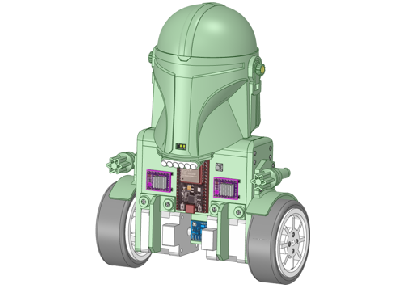
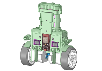
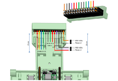
All of the robot chassis components were produced on my 3-D printer and modelled using the free 3-D design package from RS Components, DesignSpark Mechanical. Small 2x10mm self-tapping screws hold the main parts together quite rigidly. And some parts are glued together, as they would be difficult to 3-D print otherwise. RGB LEDs are mounted inside the helmet, but at a shallow depth, such that they shine through the white PLA material. The laser range finder is mounted at the base of the helmet, with the sensor looking through a small aperture. With additional code this could make the robot autonomous, capable of manoeuvring objects, and navigate round them.
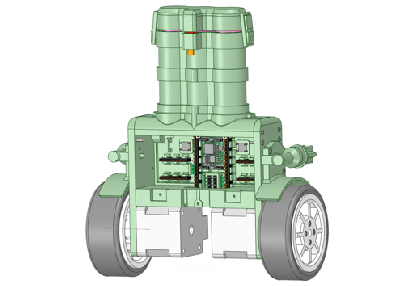
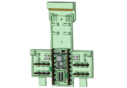
This design mounts the electronic components on a chest plate, so they are easily connected together using wire wrap technology. Whilst this approach requires a small amount of investment up front, it makes the wiring process very straight forward, and has the advantage that the built unit can be tested before final soldering.
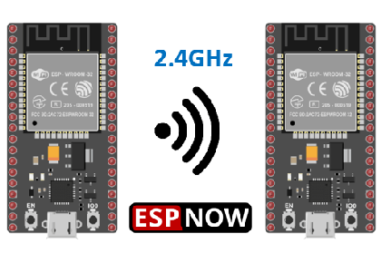
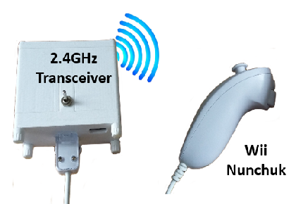
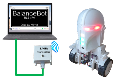
One of the great thing about ESP32 microcontrollers is there built in Wi-Fi circuitry, which makes it relatively easy to include ESP-NOW for Wi-Fi communications. As with many of my later projects, the MandalBot can be controlled from a Wii Nunchuk controller, connected to a WEMOS D1 mini transceiver unit. The protocol I have developed not only provides a control channel, it also includes a bi-directional transparent data channel, offering many forms of telemetry, as seen later with the Monitor+ application..
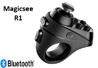
If the robot is powered up, or released from RESET, whilst the right-hand button switch is pressed, then the code adopts Bluetooth as the Wi-Fi protocol. In this case it allows you to connect a Magicsee R1 controller. This might be just what you want, but the downside is that you lose the telemetry feature; and having both ESP-NOW and Bluetooth available consumes a lot of programme memory. Therefore the code has to be compiled using the ‘Huge’ code profile in the IDE. Of course, you could remove one of these options.
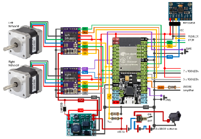
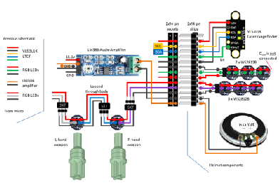
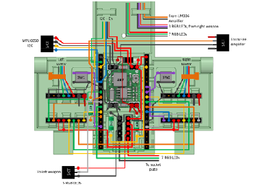
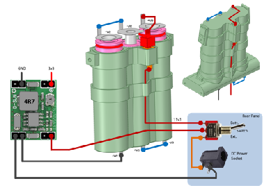
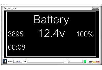
The circuit diagram for the robot is shown here on the left, with the ESP32 connected to the two stepper motor drivers, the MPU 6050A 3-axis gyroscope and two button switches. As the RGB LEDs can draw a relatively large current from the 3v3 supply rail, this design uses a 3v3 buck voltage regulator, to step-down the 11.1v battery voltage needed by the NEMA14 stepper motors. A resistive voltage divider feeds the microcontrollers ADC with a sample of the battery voltage, keeping a close eye on battery voltage.
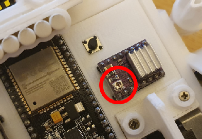
The DRV8825 stepper motor drivers have current sensing, to control the amount of energy being fed into the motors, and the boards have a small potentiometer for adjustment. To aid setting this current limiting up, for each driver board, the robot can be fed power from an external DC power supply via a socket, mounted on the rear of the robot. If the current is too small, the stepper motors will have limited torque; where as if it is too large, the motor will run very hot and could be permanently damaged, relatively quickly.
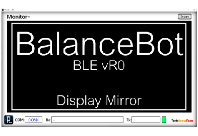
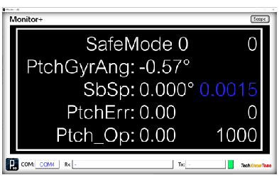
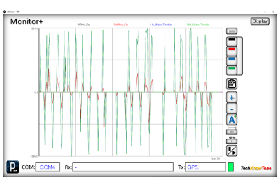
For projects incorporating a 128x64 OLED display, I developed a monitoring app that could convey the display contents back to a PC, and then onto a large monitor for folk to see. I then realised that this useful feature could also be used on projects not including an OLED display, and from then on this Monitor+ app was developed. Simply put, over Wi-Fi the code in the ESP32 can send the contents of numerous displays, to be shown in the monitor app. This could include text, and also data, to be displayed like the serial monitor as waveforms.
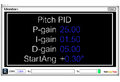
With this system you can now click on the left or right-hand side of the Monitor+ display to tell the code in the microcontroller to present different display content, and with coloured text (in this case blue) you can make numeric fields adjustable with the click of the mouse. In this project I have a display for PID controller coefficients, which you can adjust in real time, whilst the robot is self-balancing. Best of all, you can code and include more displays, and could use this approach in other projects you might develop. It’s quite easy to adapt..
Design Files
The following files can be downloaded to help you complete this project. Each has a hyper-link and an associated description. Depending on how your web browser is configured the links will either open the files directly into your browser or offer them as downloads. Note that to get the most from this project, you will also need to build the Wi-Fi controller project. This enables the use of Nunchuk control and the Monitor+ app, making PID tuning much more achievable.
Circuit Diagrams - a drawing of what is seen in the view above. Use it as a guide to wiring up your project. Updated: 26/11/2025
Parts List- the things you will need and budget prices.
3-D Parts - images showing you what the 3-D parts look like. To be expanded to include the ‘head’ shortly.
3-D Models - a zip file containing all of the STL files, which you can use with a slicer application.
Software Code - the all important Arduino .ino files. Several files from a tabbed IDE, all must be included to compile this code. Updated: vR2, 2024/11/24.
Monitor+ App - these are run-time versions of my Monitor+ app. Both 32-bit and 64-bit versions are provided for Windows pcs. Updated: 2024/07/15.
Demo Functions - a video showing the sequence of taking the robot into self-balance mode..
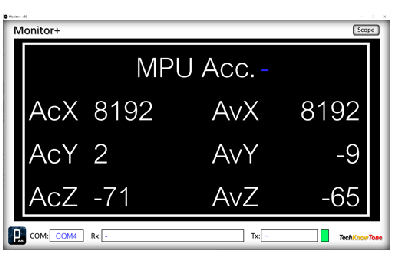
Calibration - a pdf explaining how to record and remove MPU6050 offsets, to improve sensor accuracy. Updated: 26/11/2025.
Libraries
This ESP32 project relies on the use of seven libraries, <Arduino.h>, Wire.h, <FastLED.h>, "BLEDevice.h", <esp_now.h>, <WiFi.h>, and "SparkFun_VL53L1X.h" which are included in the IDE set-up, but may need to be installed using the library manager. The Wire.h library provides the interface for I2C devices used in the robot and the controller. You have two in this project, one being the MPU6050 3-axis Gyro and the second being the VL53L1X range finder. See notes below regarding the need to calibrate the stepper motor drivers and the balance point of your robot.
Design Notes:
The following notes will help you understand how the files in this project work or can be used in principle. Each note has a bold heading for quick reference and they are listed in alphabetical order.
.ino File - the zip file contains several folders, which in turn contain the source code files. Therefore you will need to unzip it to use it.
3-D Models - the constructions of this design is based on the use of 2 x 10 mm metal dolls house screws, M3 x 30 mm nylon countersink screws, and 2-part epoxy glue.. The 3-D Parts document identifies all of the parts to be printed, as well as their hole and tap sizes. It is important to ensure that pilot holes have not shrunk during printing, by hand drilling them to he correct size.
Calibration - You will want to calibrate the stepper motor driver currents, to prevent wasting power and overheating. Start with the potentiometers turned fully clockwise (minimum current) then turn slowly counter-clockwise to increase the current. I set mine to between 150 - 200 mA for each motor. You will also need to set the calibration value for the accelerometer to determine the vertical position. Ensure that the MPU6050 board is parallel with the line of the robots body. Then find the balancing point of the robot and get the reading from the Monitor+ app. Text that is displayed in blue can be clicked on to change the value of variables in the code, like PID controller coefficients. This can be done over Wi-Fi, whilst the robot is active, and then later included in the source code using the Arduino IDE..
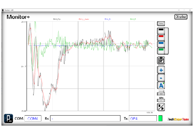
Demo - as the role of this robot is to act as a demonstrator, it is possible to adjust or even switch OFF the gains in the PID controller using the Monitor+ app. This enables you to demonstrate the effects of the proportional, integral and derivative terms of the PID controller. You can also display variables and even plot them in real time; showing gyro response to the robot being pushed for example
Need more?
If you feel that I haven’t included enough information to allow you to tackle a project of this type then send me an email explaining what you need. Or if you just want to give me some general feedback on this site, or to suggest projects what I might include which would be interesting to you, I’d be pleased to hear from you.
Page updated: 26/11/2025