
- Project
BalanceBot Mk1
Building on the success of my earlier self-balancing robot in 2017, I decided to design a new one using the ESP32 microcontroller, with DC motors and a 2.4” display to give the robot ‘personality’. It performs well and there is plenty of scope for you to modify and extend this project, so why not give it a try.
Project Overview
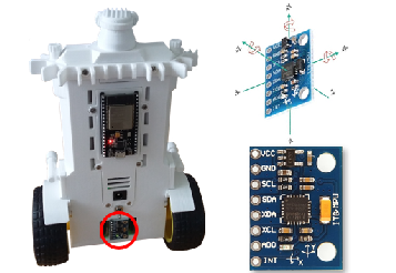
This robot uses two DC motors, to drive the wheels, and a micro-servo to rotate the head, which contains a laser range finder. Each motor has an optical slot sensor, so we can track motion. The self-balancing system is achieved using a low cost MPU6050 sensor, read over I2C. Expressions of happiness and concern are created in the form of a face, on a 2.4” colour display. Once in balance mode, the robot can be driven around using a 2.4GHz Wi-Fi link and a Wii Nunchuk controller, which is covered as a separate project here.
Click on the image to the right to see the robot being put through its paces. The battery monitoring system gives a good indication of battery capacity and remaining life.

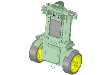
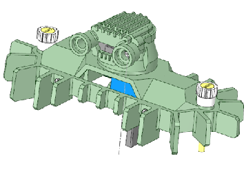
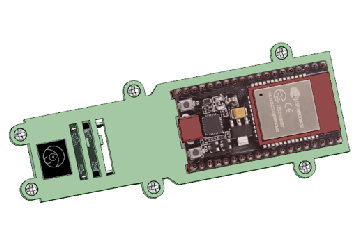
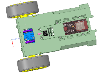
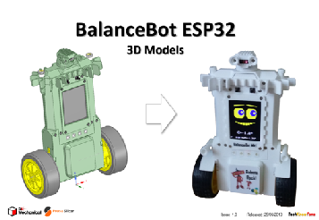
The design was created using a 3-D modeller and printer, to ensure that the assembly goes together with ease. The top of the robot has a stylish bounce ring, to prevent damage should it falls over; useful when you are tuning the controller for self-balance. This also acts as a battery cover, which tilts back to aid extraction and charging. The ESP32 micro is mounted on the rear of the body, along with an ON/OFF switch, and the all important MPU6050 sensor.
There is plenty of scope for tailoring the robot; I’ve added mudguards and side guns, but you could add much more. You just need to bare in mind keeping the centre of gravity towards the centre of the body. The 2.4” colour display, with facial expressions, and the programmable RGB LEDs really make this little robot come alive.
The BalanceBot code enables it to be linked to two Windows based app, over the USB serial link or Wi-Fi via the controller. I developed these time saving Windows apps in ‘Processing’ and you can download their Java executable files from a link below.
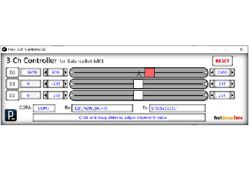
The simpler of the two apps enables you to control the head servo motor and wheel motors, using sliders to set their values. With this you can determine limits for the head servo and ensure that your wheel motors are turning correctly, and look at break-away friction values.
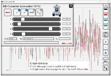
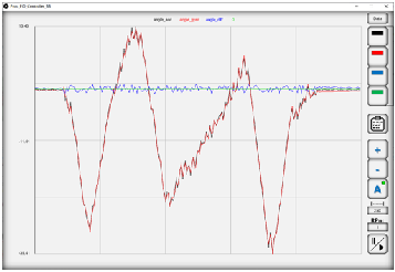
The second app aids you in setting the PID controllers coefficients, which is essential to achieving self-balance. You can also use a graphing function which plots data received from the robot, in real time and even over the Wi-Fi link. So you can even observe gyroscope and accelerometer outputs whilst the robot is self-balancing. How cool is that!
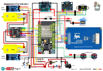
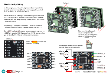
The circuit diagram is shown here on the left, with the ESP32 micro connected to the 2 DC motors via H-bridge drivers, using PWM. To reduce the strain on the micros regulator, I have used a separate 3.3v DC-DC converter. The MPU6050 3-axis sensor and laser range finder are connected over I2C, and the 2.4” colour display gets its data over the SPI link. Whilst battery powered, the robot can also be powered from a mains adapter during testing.
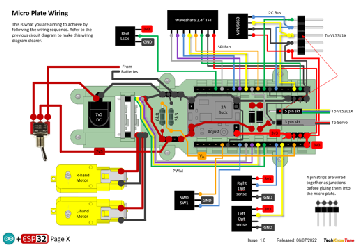
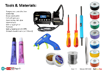
In construction I use wire wrap technology to make the wiring process easier and more reliable. This allows you to test your circuits before applying a soldering iron, avoiding any difficult to correct errors. There is however an initial outlay in buying the wrapping tool and spools of wire.
I took photos during the construction which should help you follow the sequence and see how wires are formed and run.
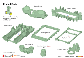
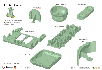
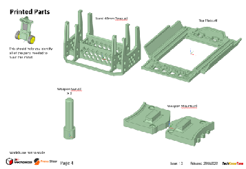
All of the 3-D models are provided as STL files, zipped together into one file. They can therefore be used with a slicing application of your choice, to create the g-files for use with a 3-D printer. For my project I used PrusaSlicer, which is a free download from the internet.
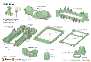
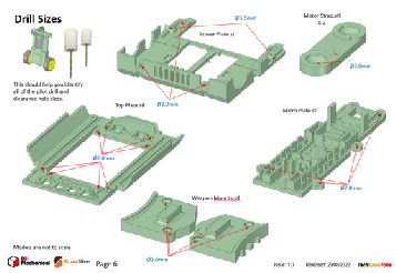
The pdf file provided will help you identify the stl models, and it also shows the sizes of pilot and clearance holes needed for screws, as well as M3 tapped holes.
The project is meant to be built in two parts, one being the BalanceBot MK1 robot and the other being the Wii wireless control box. You will need to download models and instructions for that project from this page here. Whilst the BalanceBot Mk1 does self-balance in stand-alone mode, without doubt the use of the Wii Nunchuk and wireless link are great additions to this project. The wireless project is also used with several other projects, and is likely to be needed for others in the future.
Design Files
The following files can be downloaded to help you complete this project. Each has a hyper-link and an associated description. Depending on how your web browser is configured the links will either open the files directly into the browser or offer them as downloads.
Circuit Diagram - a detailed pdf of what is seen in the view above. Use it as a step by step guide to wiring up your project. Updated: 25/11/2025.
Parts list - the things you will need and budget prices, Wii Nunchuk WiFi controller not included; see separate project.
3-D Models - a zip file containing all of the STL files, which you can use with a slicer application.
3-D Parts - a pdf file which identifies the 3-D parts, their critical features and how to prepare them for assembly
Software - the all important code, .ino files for BalanceBot Mk1 and WiFi transceiver, plus two ‘Processing’ apps. Update: vR2. 5/12/2025.
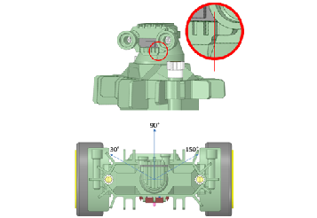
Calibration - shows the critical angles you need to enter into your code to calibrate head servo motor and DC wheel motors. Updated: 25/11/2025.
PID Controller - a pdf explaining the main features of the PID controller app.
Demo Functions - a pdf explaining the functions available with buttons and when using a Wii Nunchuk controller. Updated: 5/12/2025.
Libraries
This project relies on the use of ten libraries, <Arduino.h>, <HardwareSerial.h>, <ESP32Servo.h>, <Wire.h>, <FastLED.h>, "SparkFun_VL53L1X.h”,<esp_now.h>, <WiFi.h>, <Adafruit_GFX.h>, <Adafruit_ILI9341.h> which need to be included in the IDE set-up, in order for the .ino code to compile correctly. If you haven’t used an ESP32 before with the Arduino IDE, then you will need to install the board libraries too. There are several articles on the web that explain this process.
Design Notes:
The following notes will help you understand how the files in this project work or can be used in principle. Each note has a bold heading for quick reference and they are listed in alphabetical order.
.ino File - the software .zip file contains three folders: Balance_Bot_Mk1_R0, Proc_3Ch_Controller_00, and Proc_PID_Controller_BB, which in turn contains several files. These are all to be extracted and retained within the same folders, of those named. If you are wondering why there are several .ino files, it is because I use the tabbed interface within the Arduino IDE, and for each tab there is a corresponding .ino file. The two controller apps are compiled in a Java version, which will run without installation, once decompressed from the zip file into normal folders.
3-D Models - this design is based on the use of 2x10 mm steel countersink screws. The pdf files provided should give you sufficient information to identify the parts and indicates the quantity of each to be printed. It also defines the size of pilot holes for screws, which may print under size.
Calibration - It is essential that you undertake a calibration exercise, in order to enter the correct values into your .ino file, as servo values can vary widely. The more accurately you perform this important process, the better the performance of the robot.
Serial Port - is used in this design convey readings and commands to the BalanceBot, and for general debugging purposes. Being able to see the values being applied is very useful and essential to calibration. If you also build the WiFi Transceiver project you will be able to connect that unit to your PC via USB and communicate wirelessly with the BalanceBot MK1.
STL Model Files - use these with your favourite slicer application. In the 3D Parts pdf document I have indicated the size of pilot holes needed for the screws. The design is based on a 1st layer height of 0.3mm, and subsequence layer heights of 0.15mm or 0.3mm depending on the print quality you wish to achieve.
Need more?
If you feel that I haven’t included enough information to allow you to tackle a project of this type then send me an email explaining what you need. Or if you just want to give me some general feedback on this site, or to suggest projects what I might include which would be interesting to you, I’d be pleased to hear from you.
Page updated: 5/12/2025