
- Project
QuadAuto (ESP32)
Given the success of my earlier Arduino based quadrupeds, I decided to design one using the ESP32 microcontroller. With built-in Wi-Fi and a more powerful dual-core micro, this delivers a robot which performs well, and has significant scope for code development. You will want to build the robot and the separate Wi-Fi transceiver project, covered separately.
 |
|||||
|
Project Overview The 2.4GHz Wi-Fi link provides a reliable way of controlling its behaviour, using a Wii Nunchuk controller. It also enables code in the robot to send messages, to be displayed in a custom Windows app. This robot can walk and steer normally, and sideways like a crab, and perform custom moves using the Nunchuks ‘C’ and ‘Z’ buttons. Check out the video link opposite. |
|||||
|
|
|||||
|
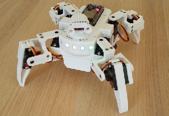
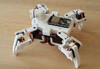
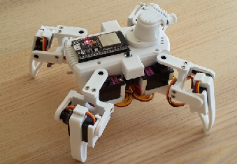
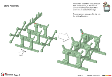
With walking robots it’s important that the design is as light as possible, and well balanced in terms of its centre of gravity. If the robot is too heavy it will struggle to get off the ground, and consume a lot of battery power; and if it is not balanced it will tend to rock badly when walking and turning. I decided to make this design very symmetrical, such that it can walk in all four directions with equal ease. Cable management is another thing to consider when making a small robot, as servo motor leads are deliberately long for use in model aeroplanes, so it can be quite tricky trying to effectively lose them within the design, without them appearing untidy. The design of a simple stand is also included with the 3D models, which is just sufficient to raise the robot a few millimetres off the ground, making it ideal for testing in a safe low power way. |
|||||
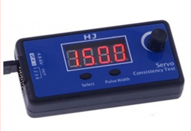
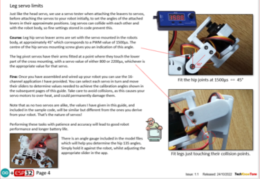
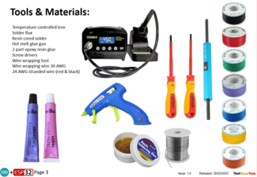
Calibration of each servo motor is key to robot performance, and I’ve tried to make this straightforward for you. When building your robot, you use a servo tester to set approximate leaver positions, which is simple to do; they are cheap to buy and very useful for other projects involving servo motors.
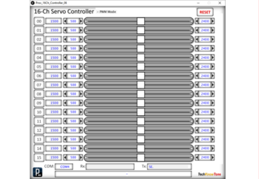
Then once you have built and wired up your robot you can complete the calibration process using a Windows based app I have written, and given you for free. This tool is not only a great aid for this project, you could use it in other servo based projects too. You simply determine the servo angles and limits, then add them into the code as shown. Your robot will then perform in exactly the same way as mine. If you have a Mac, and can’t run the app, then you can still use the servo tester for this part too.
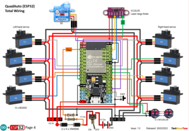
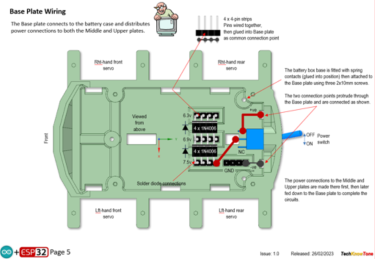
The circuit diagram is shown here on the left, with the ESP32 connected to the eight servo motors; with 6v power being fed to the servos from a diode voltage dropping circuit. Servos will normally operate between 4.8v and 6v, but they work much better at the higher voltage. Note that this circuit assumes an input voltage of 7.5v from a power plug or 7.2v from a 2 x 18650 Lithium rechargeable battery pack. These batteries work really well, but you need to avoid those with built in circuit protection, as they will current trip.
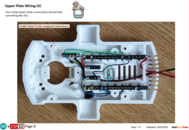
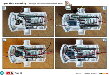
To avoid running the batteries flat and damaging them the code constantly checks the voltage, and enters a safe mode should a low voltage condition occur. I’ve also included photos of how I wired mine up, to help you with the wiring, which can be a little tricky if you are new to using a soldering iron. The wiring process does rely on the use of wire wrap wire, which makes the process simpler, and you can test before soldering the joints.
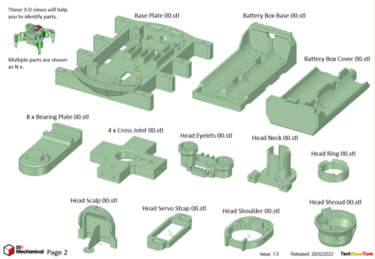
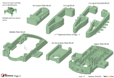
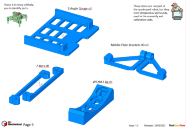
All of the 3-D models are provided as STL files, zipped together into one file. They can therefore be used with a slicing application of your choice, to create the g-files for use with a 3-D printer. For my project I used PrusaSlicer, which is a great app and a free download from the internet. Models for assembly aids are also included.
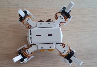
I’ve also provided a pdf file showing you the names of each component and the quantities you need to print of each. The design is essentially held together using 2 x 10mm self-tapping dolls house screws, making it strong and rigid, whilst still being able to take it apart should you need to changed a component. The legs are easily removed and replaced, so you could play around with different designs, like rubber pads to offer more grip. Two styles of leg are provided, one plane and the other with serrated teeth.
Design Files
The following files can be downloaded to help you complete this project. Each has a hyper-link and an associated description. Depending on how your web browser is configured the links will either open the files directly into the browser or offer them as downloads.
Circuit Diagram - a drawing of what is seen in the view above, plus veroboard wiring. Use it as a guide to wiring up your project.
Parts list - the things you will need to build this project. You will also need to make the WiFi transciever project here..
3-D Models - a zip file containing all of the STL files, which you can use with a slicer application.
3-D Parts - a pdf file which identifies the 3-D parts, and the quantities of each you will need to print.
Software Code - the all important Arduino .ino file which runs the project and ‘Processing’ application. See comments below on coding.
Calibration Record - shows the angles you need to determine and enter into your code to calibrate new servo motors.
Demo Functions - a pdf outlining how you control the QuadAuto robot.
Libraries
This project relies on the use of seven libraries, <Arduino.h>, <HardwareSerial.h>, <Wire.h>, <FastLED.h>, <ESP32Servo.h>, <esp_now.h>, <WiFi.h> which may need to be included in your version of the Arduino IDE set-up.The RGB LEDs are controlled using the FastLED functions and the Wi-Fi link relies on the use of the ESP-NOW protocol.
Design Notes:
The following notes will help you understand how the files in this project work or can be used in principle. Each note has a bold heading for quick reference and they are listed in alphabetical order.
.ino File - when you download this .zip file, and unzip it; the code project folder contains several .ino files. This is because I use the tabbed interface of the IDE, which saves a separate .ino file for each tab. You need all of these files in the project folder for the code to compile correctly.
3-D Models - this design is based on the use of 2x10mm dolls house self-tapping screws. The models have 1.5mm pilot holes for the self-tapping screws. The pdf file helps you identify all of the parts and indicates pilot hole sizes.
Calibration Record - It is essential that you undertake a calibration exercised in order to enter the correct values into your .ino file, as servo values can vary widely. Otherwise the robot will not function correctly and could even result in damage to one or more servo motors..
STL Model Files - all models are designed to be printed on a 3-D printer with a .4mm nozzle, with slicer layer heights of 0.3mm.
Need more?
If you feel that I haven’t included enough information to allow you to tackle a project of this type then send me an email explaining what you need. Or if you just want to give me some general feedback on this site, or to suggest projects what I might include which would be interesting to you, I’d be pleased to hear from you.
Page updated: 03/03/2023