
- Project
BallBot 4x4 (ESP32)- A Self-balancing Robot
Given the success of my previous BallBot projects, I decided to design a new version based on the ESP32 microcontroller, using a new motion sensor ICM-42607-P, and more powerful DC motors. This has given me a demonstrator that is great for explaining complex self balancing principles. Why not try something like this yourself?... it’s quite challenging and you’ll learn a lot from the experience.
Project Overview
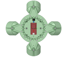
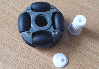
To balance on a ball you need to be able to drive it in any direction, to remain on top of it. This project uses robot omni wheels, which can be driven in one direction whilst rolling freely at right-angles. Four wheels, working in pairs, mounted at 90° to each other can therefore provide movement in any direction. The ICM-42607-P 3-axis gyroscope, and accelerometers, are used to sense the slightest imbalance, which triggers the control system to drive each motor pair to respond to the error. A 2.4 GHz Wi-Fi transceiver link is used with a Wii Nunchuk or Classic, to control the robot, and to convey dynamic data which can be displayed as graphs on a PC screen for detailed analysis, whilst the robot is moving. Click the image on the right to watch a video of this BallBot in action-->

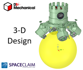
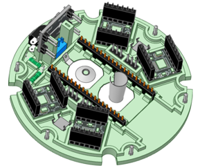
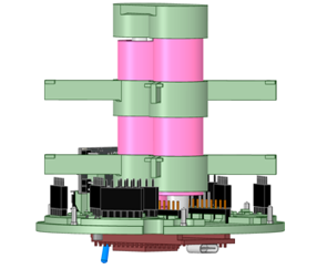
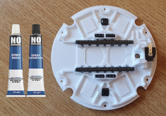
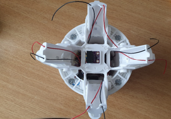
All of the robot chassis components were produced on my 3-D printer and modelled using 3-D design package, like RS Components, DesignSpark Mechanical. For this design I constructed an assembly of the complete robot, to ensure that all of the parts aligned. This included simple models of all bought components like the motors and H-bridge driver pcb’s. Given the limitations of 3-D printing, the chassis consists of a number of parts screwed together. The top micro plate mounts the majority of electronic components, with easy access to the ESP32 micro for coding updates..
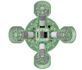
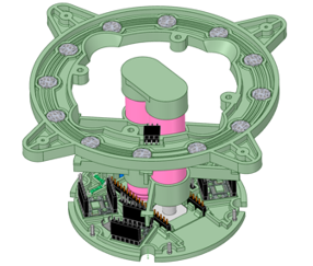
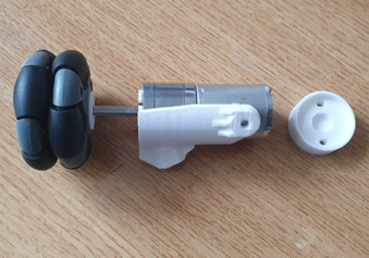
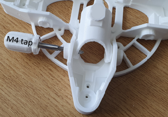
The lower body consists of two plates, to provide a strong platform on which to mount the motorized legs, which are adjustable to suit a range of ball sizes. You will need small drills, and metric taps, to be able to put threads in some of the holes in this design. The castellated crown enables the robot to be stood upside down on its head, for an automated motor and wheel demonstration.
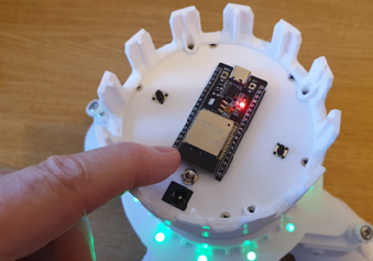
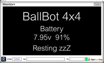
The robot is powered from two 18650 Lithium batteries, delivering 7.4v to the system. An On/OFF switch is mounted on the top plate, which gives you the ability to select power sources. The two push buttons, on the top, are for selecting screen types and invoking the self-balancing process. See the Demo Function card for more information.
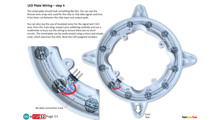
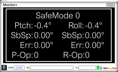
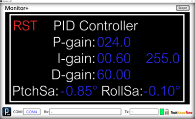
RGB LEDs are mounted on a ring, which provide moving patterns of light to indicate what the robot is doing. For example, when the robot is being moved towards vertical, as its self-balancing trigger point. The graphing app, I mentioned earlier, is also used to tune the robots PID controller, by clicking on variables presented on a PC screen. These adjustments are sent to the robot over the Wi-Fi link and their effect can be seen instantly. The ball size was chosen such that the omni wheels touch it at the 45 degree point, giving a solid grip on the ball, for driving about..
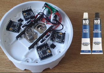

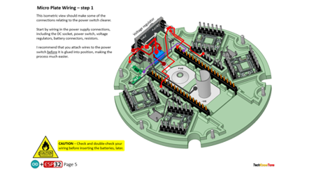
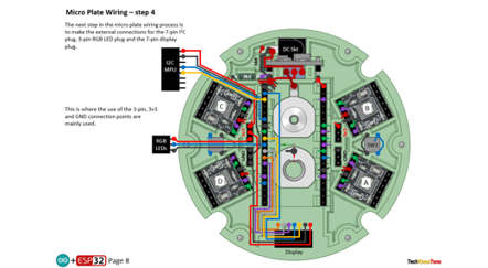
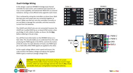
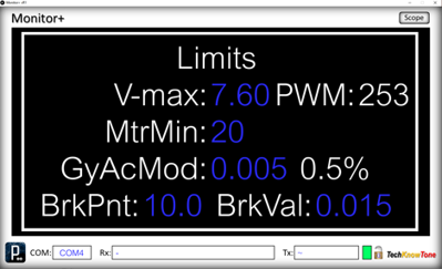
The circuit diagram for the robot is shown here on the left, with the ESP32 connected to the four H-bridge drivers, providing high current PWM for the motors, the ICM-42607-P 3-axis gyroscope and the twelve RGB LEDs, which are connected in a daisy chain fashion. As the motors are only rated up to 6v, I measure the battery voltage and adjust power accordingly. A simple resistor network is used to subdivide the supply voltage so that the ESP32 can measure the voltage remaining in the batteries, which should not be allowed to fall below 3 volts per battery, to avoid damage from deep discharge.
The round display presents an animated Cyclops eye, along with a text field displaying battery voltage. That’s always useful during demonstrations.
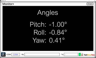
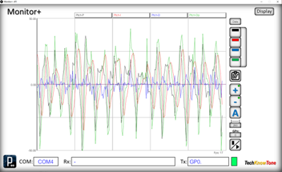
I developed the Monitor+ display and graphing tool app using Processing. This took quite a lot of effort, but the end result makes it very easy to change PID controller setting on the fly, as the robot is moving around, simply by changing numeric fields on the PC screen. You can temporarily note a set of settings you think are close to what you need, make further changes, then re-enter them later if you want them back
You can switch back and forth between controller adjustment and the graphing tool, so you can also see the effect on data sent from the robot. The Scope tool allows you to access different sets of data from the ESP32, just by clicking on a number field. The graph can be dynamically adjusted automatically, showing min/max values or set to specific ranges, and if the graph is paused you can inspect the data points simply by moving the mouse pointer over the graph, to draw on the underlying data.
Design Files
The following files can be downloaded to help you complete this project. Each has a hyper-link and an associated description. Depending on how your web browser is configured the links will either open the files directly into your browser or offer them as downloads.
Circuit Diagram - a .pdf file of drawings and photos, of the build process. Use it as a guide to wiring up your project. Updated: 25/11/2025.
Wii WEMOS D1 Transceiver - you will need a wireless transceiver to control this project. Also see this low cost alternative: Wii ESP32-C3 Transceiver.
Parts List - the things you will need to buy, and budget prices.
3-D Parts - images showing you what the 3-D parts look like, and the associated hole and tap sizes.
3-D Models - a zip file containing all of the STL files, which you can use with a slicer application.
Software Code - Arduino .ino files. Two folders, one for the robot, and one for the Monitor+ application - Updated: vR1 @05/01/2025.
Demo Functions - pdf explaining the functions available with the button switch, and when using the Wii Nunchuk controller.
Calibration - diagrams and notes created in support of calibrating the robots drive system. Updated: 25/11/2025.
Libraries
This project relies on the use of these libraries, Adafruit_GFX.h, Adafruit_GC9A01.h, FastLED.h, esp_now.h and WiFi.h which need to be included in the IDE set-up. The Adafruit libraries provide a convenient means of creating text and graphics on the round display. The FastLED library if for controlling the WS2812B RGB LEDs. The esp_now.h and WiFi.h libraries provides the interface for the Wi-Fi.
Design Notes:
The following notes will help you understand how the files in this project work or can be used in principle. Each note has a bold heading for quick reference and they are listed in alphabetical order.
.ino Files - the zip file contains several folders, which in turn contain the source code files. Therefore you will need to unzip it to use them. Note, as I use the tabbed interface of the IDE, there are multiple .ino files, one for each tab. All of these must be included for the code to compile correctly.
3-D Models - to be printed at 0.3mm layer height, or smaller. The construction of this design is based on the use of 3 mm and 4 mm nylon countersink screws, with the exception of the metal screws used to house the motors. This leads to a very clean shake-proof solution. You will need to use drills and taps to thread some of the holes.
PID Tuning - As this is the critical part of this project I used a Windows based app, called Monitor+. Which makes the tuning of the PID variables very straight forward and something you can do in real time. Look at the Calibration document for more information. Once you have arrived at a suitable set of values, for the size of ball you have chosen, you can then hard code them into the NANO code. There is a PDF file provided to explain this process.
Demo - as the role of this robot is to act as a demonstrator, it is possible to switch OFF the ‘I’ and ‘D’ gains in the PID controller by using the Monitor+ app. This enables you to demonstrate the effects of the proportional gain term of the PID controller only, which is not sufficient on its own to achieve balance.
Need more?
If you feel that I haven’t included enough information to allow you to tackle a project of this type then send me an email explaining what you need. Or if you just want to give me some general feedback on this site, or to suggest projects what I might include which would be interesting to you, I’d be pleased to hear from you. I can only respond to questions relating to the work I have published, and the use of components outside of scope can not be considered.
Page updated: 25/11/2025