
- Project
Wii ESP32-C3 Transceiver
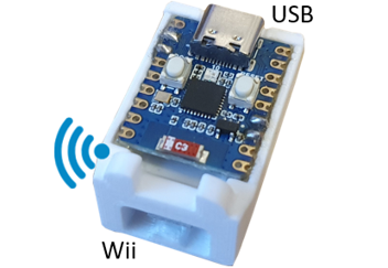
Given the relatively high cost of the WEMOS D1 transceiver, I decided to make a low cost version, using the minimum number of parts, and in a small form factor. Powered off a PC or USB brick battery, this device provides the essential interface between a Wii controller and your project; but can also convey data between you project and your PC. It now supporots programmable MAC addresses.
Project Overview
This Wi-Fi transceiver is low cost, and easy to make; using the minimum number of parts. It’s role is to convey demands from Wii hand-held Classic controllers, as well as act as a transparent link between your project and an application running on a PC.
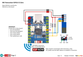
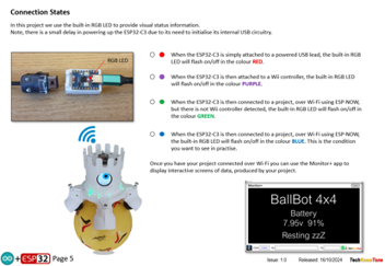
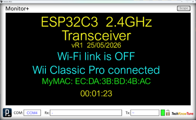
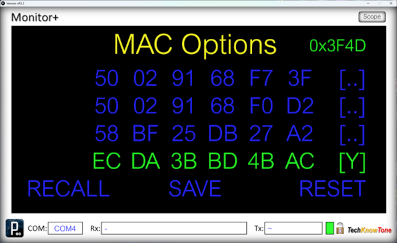
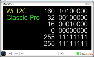
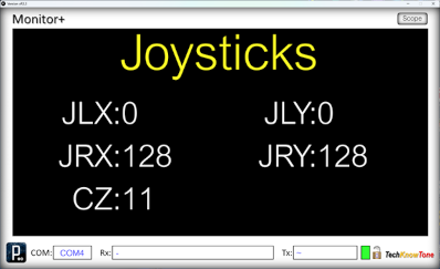
The unit detects which type of Wii controller is connected, and conveys that information in its message structure to the remote robot. The colour of the built-in RGB LED acts to confirm that connections have been made between the device, the Wii controller and the remote project. When not connected, it is now possible to assign specific MAC addresses, using the Monitor+ app as an interface. These MAC values are stored in flash EEPROM memory.
View the Circuit Diagram below, to see how easy it is to make this device; and download the 3D models to help make it. If you want a larger battery version, with a built-in display, then you could try the Wii WEMOS D1 Transceiver project as an alternative.

Design Files
The following files can be downloaded to help you complete this project. Each has a hyper-link and an associated description. Depending on how your web browser is configured the links will either open the files directly into the browser or offer them as downloads.
Here are the files you will need:
Circuit Diagram - drawings of what is seen in the views above, as a guide to wiring up this project - Updated: 25/05/2026.
Parts list - the things you will need and budget prices.
3-D Models - a zip file containing all of the STL files, which you can use with a slicer application.
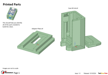
3-D Parts - a pdf file which identifies the 3-D part STL file references you will need to print.
Software Code - the all important Arduino .ino file for this project. See comments below on coding - Updated: 25/05/2026.
Libraries
This project relies on the use of several library components EEPROM.h, Wire.h, WiFi.h, and espnow.h, which all need to be included in the Arduino IDE set-up, or the compiler will throw up errors. View the full list at the beginning of the code. Note that the ESP32-C3 Zero uses built-in circuitry for the USB interface, and not a separate chip, like other versions. It is important that code is uploaded to configure this, so read the instructions at the beginning of the code.
Design Notes:
The following notes will help you understand how the files in this project work or can be used in principle. Each note has a bold heading for quick reference and they are listed in alphabetical order.
.ino File - when you download this .zip file, remember to place the files in a folder with the same name, otherwise the Arduino IDE will not load it and display an error message. The primary .ino filename must match the folders name.
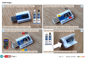
3-D Models - this design is very simple; only consisting of 3 parts. They are glued together, so there is no need for additional fasteners
STL Model Files - all models are designed to be printed on a 3-D printer with a 0.4mm nozzle, and 0.3mm layer height. If you use a printer with a finer nozzle, say 0.3mm, then this may result in the height of the components being slightly less than intended, but I would still expected them to work.
Need more?
If you feel that I haven’t included enough information to allow you to tackle a project of this type then send me an email explaining what you need. Or if you just want to give me some general feedback on this site, or to suggest projects what I might include which would be interesting to you, I’d be pleased to hear from you.
Page updated: 25/05/2026