
- Project
TankBot MK1 (ESP32)
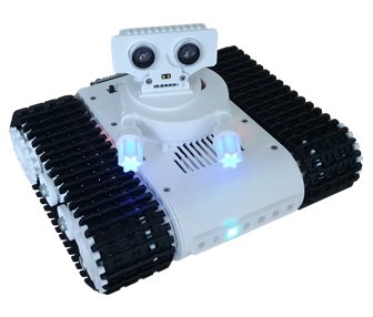
A talking tank, that can detect targets, range and engage them. Controlled using a Wii Classic controller, over Wi-Fi; you can drive the tank and control its weapon independently. With audio files, stored on an SD card, TankBot can perform to music of your choice. Given the capacity of an ESP32, there is still plenty of scope to add features of your own, or adopt the code in another project.
Project Overview
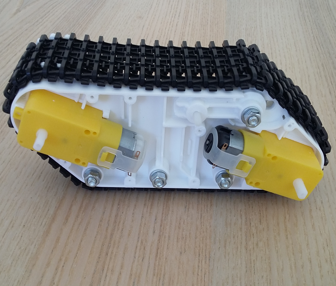
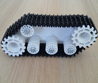
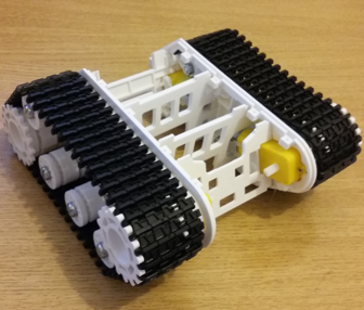
This project demonstrates how multi-tasking code can be used to control a wide range of devices, all at the same time. It uses high speed PWM to generate audio signals, read from WAV pcm files, stored on a micro-SD card, and an interrupt service routine to delver those samples at 16 kHz, to an audio amplifier. Four DC motors are used to drive the twin tracked chassis, giving it plenty of power and great manoeuvrability. The servo controlled turret, houses a laser range finder, as well as an acoustic range finder. These give TankBot a seek and destroy capability, which it can display like a radar sweep in a Windows app.
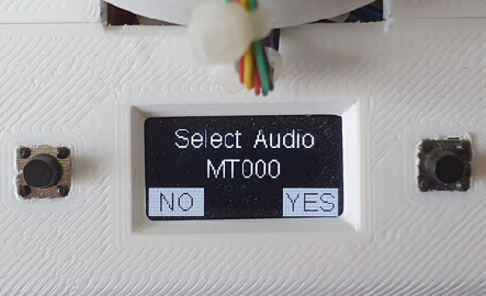
TankBot can be controlled via two push buttons, on its body, as well as by a Wii Classic controller, over Wi-Fi, using a 2.4 GHz ESP-NOW transceiver. Watch the video on the right, to learn more about this interesting project.

|
|
||||
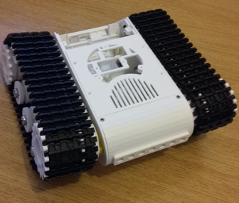
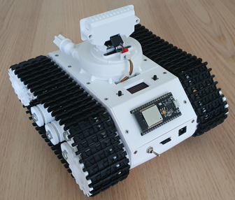
| Most of the plastic parts (with the exception of the track) were produced from 3-D models, for which STL files have been provided here. So you can print off the parts yourself and make one too. To make them easier to print, the drive wheels are constructed from several parts, glued together; as are the weapon components. The top and base cover plates are printed flat, then formed in curves using heat from a hair dryer. The top rear idler wheels are on adjustable arms, to act as track tensioners. A strip of seven RGB LEDs lie across the front of the chassis, providing feedback and coloured prompts. For example in range finder mode, the strip acts as a range bar graph, from left to right. When audio files are played using the ‘Talk Engine’ the code analyses the sound amplitude and displays this as a blue centred bar graph, giving the impression of lip movement. The turrets weapons also contain LEDs, to animate the firing effect. Sounds exit the chassis through a grill in the bodies top surface. |
||||
|
|
||||
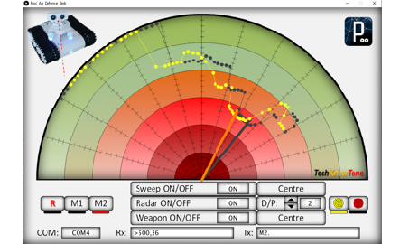
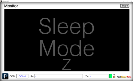
| Whilst this robot has a 64x128 OLED display, it can also be used in conjunction with a Windows PC, running the Monitor+ app. This app was written originally to show what is actually being displayed on the OLED to an audience, This all works over Wi-Fi, and the screens presented are all generated by the code in the ESP32, and accessed by simply clicking on the displays screen; providing access to additional screens not normally displayed when using the push buttons alone. A separate ‘Air Defence’ app is also provide, to demonstrate the robots ‘seek and destroy’ features. These apps were written in C++ using a coding environment called Processing; which runs directly on a Windows PC, and can also be exported to standalone Java programs. The standalone versions are provided with the project, to download. |
||||
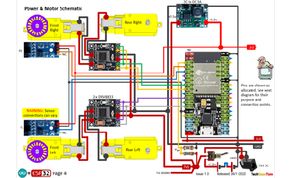
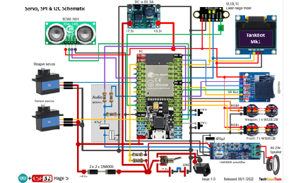
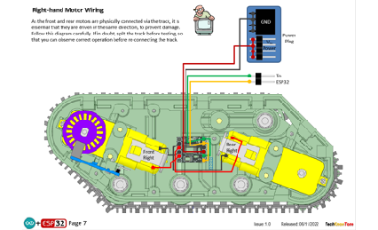
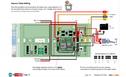
The circuit diagram shows the wiring of the TankBot, in which the physical circuitry is distributed around the body. This is done to make the wiring task simpler and more maintainable. Slot sensors are only employed on the front wheels, as the track binds together the front and rear motors. As most of the circuitry works at 3.3v the acoustic range finder is a RCWL-1601, and the WS2812B LEDs work from this voltage too. More of the battery voltage is fed to the servo motors and audio amplifier module
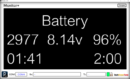
The 18650 battery voltage is converted to 3.4v in a buck regulator, for efficiency; and the battery voltage is monitored by the ESP32, and displayed in the OLED and Monitor+ app, when connected to a PC. A DC power socket is included, so that the unit can be powered for prolonged periods during software development, and placed on a stand, such that the drive system can be operated, without the TankBot moving
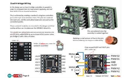
The PWM driver boards, for the DC motors, are stacked together to increase the current drive capability.
All of the 3-D models are provided as STL files, zipped together into one file. They can therefore be used with a slicing application of your choice, to create the g-code files for use with a 3-D printer. For my project I used PrusaSlicer, which is a great app and a free download from the internet. Models for assembly aids, and testing are also included.
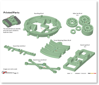
I’ve also provided a pdf file showing you the names of each component and the quantities you need to print of each. The design is essentially held together using 2 x 10 mm self-tapping dolls house screws, making it strong and rigid, whilst still being able to take it apart, should you need to changed a component. The base of the chassis houses a removable battery plate, holding two 198650 Lithium batteries. You will need a good quality battery charger for them.
The 3-D parts document details the pilot hole sizes needed for each piece, and also helps you to identify all of the printed components. The modelling assumes a 0.4mm nozzle size on the 3-D printer.


Design Files
The following files can be downloaded to help you complete this project. Each has a hyper-link and an associated description. Depending on how your web browser is configured the links will either open the files directly into the browser or offer them as downloads. Note that these documents only refer to the PIX lamp robot. You are likely to want to make the Wi-Fi D1 Transceiver project as well, in order to use Monitor+ app with it.
Circuit Diagrams - drawings of what is seen in the views above. Use it as a guide to wiring up your project. Updated: 08/12/2025.
Parts list - the things you will need to build this project. You will also need to make the WiFi transciever project, found here..
3-D Models - a zip file containing all of the STL files, which you can use with a slicer application.
3-D Parts - a pdf file which identifies the 3-D parts, pilot drill sizes, and the quantities of each you will need to 3-D print.
Software Code - the all important code files, which runs the project, and ‘Processing’ apps. See comments below on coding.
Audio Files - a set of WAV pcm files, plus instructions on how to add mode.
Calibration Record - explains how you determine limits for the turret servos, and calibrate the battery voltage measurement. Updated: 08/12/2025.
Demo Functions - a pdf outlining how you control the PIX lamp robot.
Libraries
This project relies on the use of nine libraries, <FastLED.h>, “FS.h”, “SD.h”, <ESP32Servo.h>, “rtc_wdt.h”, “SDD1306Wire.h”, “SparkFun_VL53L1X.h”, <esp_now.h>, <WiFi.h> in the TankBot MK1 code, which may need to be installed in your version of the Arduino IDE set-up.The RGB LEDs are controlled using the FastLED functions and the Wi-Fi link relies on the use of the ESP-NOW protocol. Note that Tabs have been used within the IDE, to simplify editing, so there is a separate .ino file for each of the six tabs. All of which must be included in the TankBot_ESP32_R0 folder,
Design Notes:
The following notes will help you understand how the files in this project work, or can be used in principle. Each note has a bold heading for quick reference and they are listed in alphabetical order.
Software Code - when you download this .zip file, and unzip it; the folder extracted contains several folders as follows:
Proc_Air_Defence_Tank_x64 -,an app, which interacts with the TankBo, over USB, turning it into an air defence system..
Proc_MonitorPlus_x64 - a display monitor app, compiled for x64-bit PCs, used to display OLED information to an audience.
Proc_TankBot_Controller_x64 - an app with slider controls, used in servo calibration.
TankBot_ESP32_R0 - a set of .ino files which combine, as the code for the ESP32 micro in the TankBot.
Note that the .ino folder contains several files. This is because I use the tabbed interface of the Arduino IDE, which saves a separate .ino file for each tab. You need all of these files in the project folder for the code to compile correctly. Also, at the start of the code, in library declarations I have indicated which version of the library I used. If you experience any problems with the compiler, ensure that you are using the same library versions as I did.
3-D Models - this design is based on the use of 2x10mm dolls house self-tapping screws. The models have 1.5 mm pilot holes for the self-tapping screws. The pdf file helps you identify all of the parts, and indicates pilot hole sizes.
Calibration Record - It is essential that you undertake calibration tasks, in order to enter the correct values into your .ino file. Otherwise the robot will not function correctly and could even result in damage and over-heating of the servo motors.
STL Model Files - all models are designed to be printed on a 3-D printer with a 0.4 mm nozzle, with slicer layer heights of 0.3 mm.
Need more?
If you feel that I haven’t included enough information to allow you to tackle a project of this type then send me an email explaining what you need. Or if you just want to give me some general feedback on this site, or to suggest projects what I might include which would be interesting to you, I’d be pleased to hear from you.
Page updated: 08/12/2025