
- Project
Sumo Robots
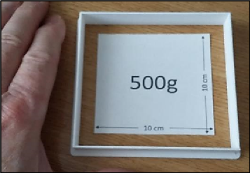
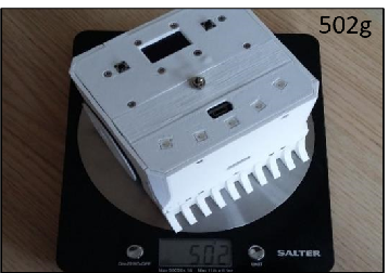
Sumo robot competitions are extremely popular in Japan and the USA, as they offer a range of interesting technical challenges for young engineers to overcome. So I decided to make one myself, to see how difficult this might be. This project focuses on the mini class of robot, which in some ways is harder to tackle, given their small volume and weight constraints imposed.
 |
||||
| Project Overview Watch the video on the right to see how they perform, and gain an insight into the technologies mentioned above. |
||||
|
|
||||
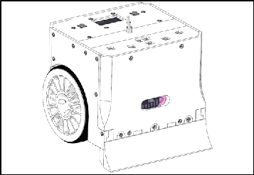
| The design aims to make their centre of gravity as low as possible, whilst making the most of the available footprint area. The wheel tyres are made from several O-rings and I’ve used LX-16A digital servos, as they provide plenty of torque combined with great control characteristics. The microcontroller used is an ESP32, which is a dual-core 32-bit device running at 80 MHz. This ensures that you have plenty of code space to play with for the hunt and kill algorithms, whilst performing all of the sensor reading activities. The device can also be controlled manually using a Wii Nunchuk controller and a wireless link using the ESPNOW communications protocol. This in turn provides a telemetry channel, which can stream sensor data from the robot to a PC in real time, to help with code development. |
||||
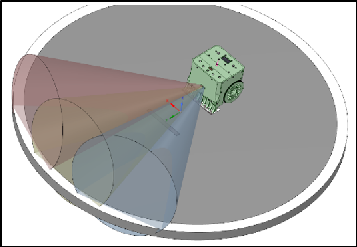
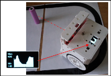
The laser range finder achieves a repetition rate of 30 Hz and is accurate to a few millimetres. It is mounted on a servo drive gimbal, which can be driven in a sweeping motion, to give it a good field of view. The microcontroller is able to store successive ranges in RAM, and build up a picture of potential objects, which the code analyses and converts it into a steering vector.
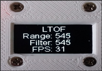
The 64x128 pixel OLED display is then able to present this target information in different forms, including simple histograms. Analogue data, taken from the infra-red sensors mounted on the base of the robot, can also be displayed. Thresholds for edge detection can be determined automatically and stored in EEPROM, so there is no need to manually adjust the sensors, its all done in code..
The display also provides a five second count down 5 - 0 prior to entering Sumo competition mode, and displays useful information on the internal workings of the code..
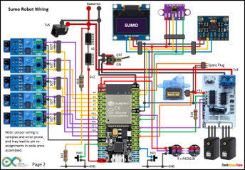
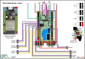
The circuit diagram is shown here on the left, with the ESP32 micro connected to the two servo motors on the right, and the five infra-red edge detection sensors on the left. The display, laser range finder and 3-axis gyroscope are connected using the I2C bus interface. The unit is powered from two rechargeable batteries, connected in series, delivering nominally 7.4 volts to the servos, which are 12v tolerant. As the micros 3.3v regulator tends to run hot, we drop some of the supply voltage to the micro using a couple of diodes.
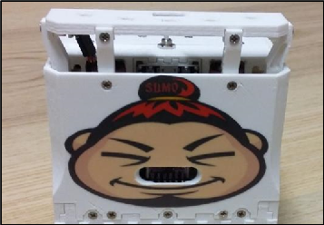
A strip of five programmable RGB LEDs are mounted on the top face of the robot. Depending on the mode of operation, these lamps provide the user with clues as to what the robot is sensing as it moves around the ring, and whether the robot is in hunt or targeting mode..
Button switches either side of the display support a click and select menu system.
All of the 3-D models are provided as STL files, zipped together into one file. They can therefore be used with a slicing application of your choice, to create the g-files for use with a 3-D printer. For my project I used PrusaSlicer, which is a free download from the internet, but there are many other free applications to choose from.
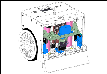
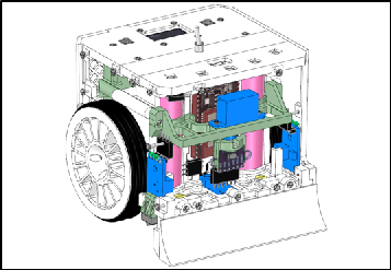
The robot is assembled from a series of plates, building from a base plate that mounts the two servo motors. When programming the ESP32 it is necessary to access the button switches on the micro, so to achieve this, small mounting posts can be inserted to raise the front top cover.
The unit is effectively held together with small 10mm dolls house screws, making it relatively easy to assemble; quite robust and relatively easy to disassemble as necessary.
Design Files
The following files can be downloaded to help you complete this project. Each has a hyper-link and an associated description. Depending on how your web browser is configured the links will either open the files directly into the browser or offer them as downloads.
Circuit Diagram - drawings of examples seen in the views above. Use it as a pdf guide to wiring up your project. Updated: 08/12/2025.
Parts List - the things you will need and budget prices. Note this does not include the Wii Transceiver parts.
Templates - Sumo labels produced in Ms PowerPoint to make your Sumobot look more interesting.
3-D Models - a zip file containing all of the STL files, which you can use with a slicer application.
3-D Parts - a pdf file which identifies the 3-D parts, their critical features and how to prepare them for assembly.
Software Code - the all important ESP32 .ino files, and a ‘Processing’ application. See comments below on coding - updated 03/2023.
Calibration - a pdf file explaining how to set up and calibrate the two LX-16A servos, and pan gimbal servo for the laser range finder. Updated: 08/12/2025.
Demo Functions - a pdf briefly explaining how to control the Sumo robot - updated 03/2023.
Libraries
This project relies on the use of nine libraries, <Arduino.h>, <HardwareSerial.h>, <ESP32Servo.h>, <Wire.h>, "SSD1306Wire.h", <Adafruit_NeoPixel.h>, <esp.now.h> , <WiFi.h> and <EEPROM.h> which need to be included in the Arduino IDE set-up. If you haven’t used an ESP32 before with the Arduino IDE, then you will need to install the board libraries too. There are several articles on the web that explain this process to you.
Design Notes:
The following notes will help you understand how the files in this project work or can be used in principle. Each note has a bold heading for quick reference and they are listed in alphabetical order.
.ino File - the .zip file contains the source folder, which in turn contains several .ino files. These are all to be extracted and retained within the same folder, of that name. If you are wondering why there are several .ino files, it is because I use the tabbed interface within the Arduino IDE, and for each tab there is a corresponding .ino file.
3-D Models - this design is based on the use of 3mm nylon countersink screws with niloc nuts as fasteners. This leads to a very clean solution as the length of each screw can be easily trimmed adjacent to the nut using wire cutters.
Code - the main code runs on a single core of the ESP32 in a multi-tasking way, which allows for the reading of sensor and display updates to run as independent tasks from the main Sumo logic. If you decide to use ESPNOW WiFi with this project, you will also need to construct the Wii Transceiver project, which enables you to steer the Sumobot using a Wii Nunchuk controller. That project can be found here.
Serial Port - is used in this design convey readings and commands over the Arduino IDE Serial Monitor, and for general debugging purposes. Being able to see the servo values being applied to each servo is very useful and essential to calibration.
STL Model Files - The forward drive arm has a hidden pocket where the plastic drive leaver from the servo motor is inserted. This is to make the part more printable, and this thin walled pocket can be easily opened up using a hobby knife.
Windows App - an app written in ‘Processing’ to provide you with a means of setting up the servos, using sliders. This was written in C++ and compiled into Java runtime. It should run on any Windows computer, with Java runtime installed. The app itself does not need to be installed and can in fact run from a memory stuck or other portable device.
Need more?
If you feel that I haven’t included enough information to allow you to tackle a project of this type then send me an email explaining what you need. Or if you just want to give me some general feedback on this site, or to suggest projects what I might include which would be interesting to you, I would be pleased to hear from you.
Page updated: 08/12/2025