- Project
Robot Hand
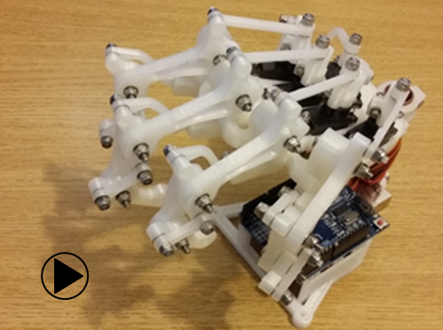
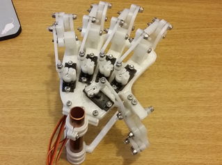
With access to a 3-D printer you can make this animated robot left hand. It uses five miniature servo motors and an Arduino UNO, and is very easy to produce.
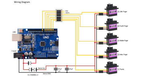
The circuit diagram is shown here on the left, with the Arduino UNO connected to the five servo motors on the right, with 6v power being fed to the servos from a diode voltage dropping circuit. Servos will normally operate between 4.8v and 6v, but they work much better at the higher voltage. Note that this circuit assumes an input voltage of 7.5v from a power plug or 7.2v from a 6 x AA rechargeable battery pack. If you want to use a higher voltage you will need to modify this circuitry to suit, otherwise you could damage your servos
It is also better not to power the servos from the UNO 5v linear regular, as any dip in supply voltage caused by loading a servo could result in the UNO being reset via its internal brown-out circuitry. Connecting one servo that way for test purposes is fine, but I wouldn’t recommend any more.
All of the 3-D models are provided as STL files, zipped together into one file. They can therefore be used directly with a slicing application of your choice, to create the g-code files for use with a 3-D printer. For my project I used Slic3r which is a free download from the internet.
The individual finger stl files consist of a group of parts nested together. They were all created from a freely available 3-D modeller application provided by RS Components, called DesignSpark Mechanical. I used the size of a miniature servo motor as the basis on which to scale the design the hand and fingers. As it turns out this gives you a hand of man sized proportions.
Design Files
The following files can be downloaded to help you complete this project. Each has a hyper-link and an associated description. Depending on how your web browser is configured the links will either open the files directly into the browser or offer them as downloads.
Circuit Diagram - a drawing of what is seen in the view above, plus veroboard wiring. Use it as a guide to wiring up your project.
Parts list - the things you will need and budget prices.
3-D Models - a zip file containing all of the STL files, which you can use with a slicer application.
Software Code - the all important Arduino .ino file which runs the project and ‘Processing’ application. See comments below on coding.
Libraries
This project relies on the use of two libraries, Servo.h and EEPROM.h, which are included in the IDE set-up. If you don’t adopt the special RESET method I use for selecting the operating mode of the robot, then you won’t need the second library, but it might be in your interest to at least study that code for future use, as it saves the need for additional circuitry.
Design Notes:
The following notes will help you understand how the files in this project work or can be used in principle. Each note has a bold heading for quick reference and they are listed in alphabetical order.
.ino File - when you download this file remember to place it in a folder with the same name, otherwise the Arduino IDE will not load it and display an error message.
3-D Models - this design is based on the use of 3mm nylon countersink screws with niloc nuts as fasteners. This leads to a very clean solution as the length of each screw can be easily trimmed adjacent to the nut using wire cutters.
Calibration - When attaching the capstans to the servo motors and setting the tendon positions it is important to set the given servo to an angle of 90° with the Servo.write() function before attaching the capstan, which in turn should be positioned at the mid-way point. Otherwise the servo may hit its internal end stop and limit the range of travel.
Need more?
If you feel that I haven’t included enough information to allow you to tackle a project of this type then send me an email explaining what you need. Or if you just want to give me some general feedback on this site, or to suggest projects what I might include which would be interesting to you, I’d be pleased to hear from you.
