
- Project
RoboDog - A wireless controlled walking robot
Given the success of the two legged biped droid I decided to design a four legged K9 variety. Like its predecessor, moving several servo motors at once, whilst maintaining balance is quite tricky. You need complex custom apps to create the moves, and that’s what I’ve done in this project. If you’d like to know more, dig into the code to see how it’s done!
Project Overview
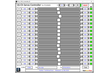
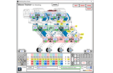
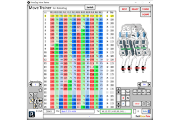
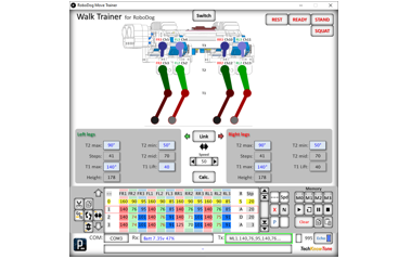
This project employs 13 servo motors, 3 in each leg, and one in its head. The microcontroller is an ESP8266, which has much more code space and RAM than a standard NANO and runs at 80 MHz clock speed. I new I would need that extra space to store the servo movements. Between the eyes is a laser range finder, which give the droid an ability to react to object being placed in front of it. Leg movements and balance are quite complex, so I wrote a custom PC app which helped me to achieve this. The droid is controlled via a Wii nunchuk, over a 2.4 GHz wireless link using the fast ESP NOW protocol. This in turn provides a bidirectional data channel for telemetry, enabling the movement trainer app to work wirelessly. If you are planning to use the PCA9685 16 channel servo driver board in another project, you might like to try the app I wrote for controlling that too. Click the image to the right to watch a video of my droid in action -->

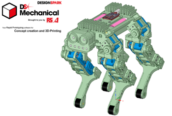
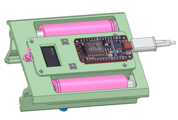
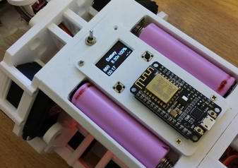
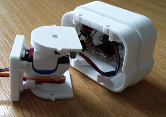
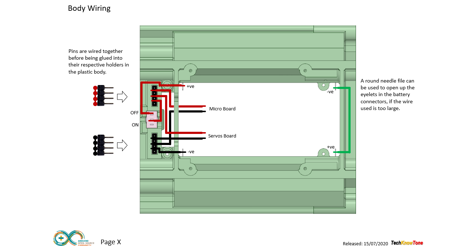
All of the robots body components were produced in PLA on my 3-D printer, and modelled using the free design package from RS Components, DesignSpark Mechanical. For this design I also constructed an assembly of the complete robot, to ensure that all of the parts aligned. This included simple models of all bought components like the servo motors and driver board. Given the size limitations of my 3-D printer, the chassis consists of a number of parts screwed together using 2 mm countersunk screws. The body top plate has compartments for the two batteries and apertures for the display and push buttons. The finned shoulders allow it to be placed on its back for testing.
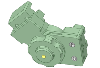
The lower legs consist of plates, to provide mounting frames for the servo motors, and joints for hip, and elbow movement. The use of screws makes it easy to maintain the robot, should you wish to disassemble it to replace a part or change its appearance in some way.
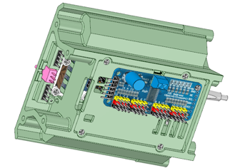
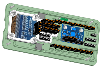
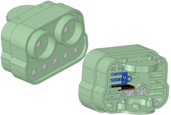
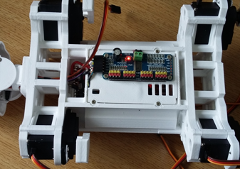
RoboDog is powered from two 18650 Lithium batteries, delivering 7.4v to the system. An On/OFF switch is mounted on its body plate, feeding power to the top plate electronics and the PCA9685 servo driver board, mounted underneath. Two push button switches sit either side of the micro, with the OLED 64 x 128 display mounted centre of the top plate. On power-up the robots servos remain inactive for safety reasons. Digital servos, like the MG996R don’t jump when power is first applied.
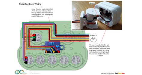
Programmable RGB LEDs are placed in each eye, and 5 in a strip on its face. The colours provide feedback on the modes of operation, and the front LEDs are animated when the robot is in motion. The servo cables are kept tidy with special clips and in compartments. The head holds a laser range finder, so that autonomous scouting behaviour can be developed with additional code.
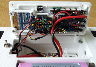
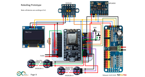
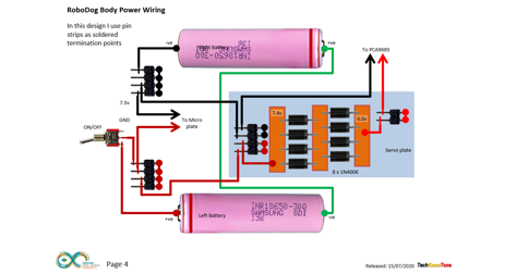
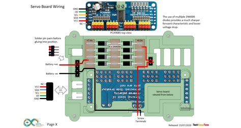
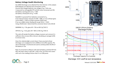
The circuit diagram for the robot is shown here on the left, with the ESP8266 micro in the centre, connected to the RGB LEDs below, the OLED display left, VL53L0X laser range finder and MPU6050 gyro above, and PCA9685 servo driver to the right. The I2C bus simplifies the wiring. As the servo motors are only rated up to 6v I have used diodes to drop the battery voltage fed to the driver board. A simple resistor network is used to enable the ESP8266 to measure the combined battery voltage, which should not be allowed to fall below 3 volts per battery; this is monitored in the code, which also predicts battery discharge life.
The built-in WiFi of the ESP8266 is significantly more robust and faster than the serial transceiver I have used in other project. You will need to make the associated wireless controller unit, which will be published separately.
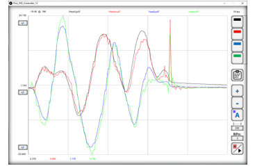
A critical step in building a project like this is in attaching the servo motors leavers and calibrating their respective angles, by recording and storing PWM values in code. To simplify this task I developed a 16 channel controller app which provides adjustable sliders for each servo. Values are then simply cut-n-pasted into your code. Then, as leg movements can be complex, having 3 servos in each, I developed a Move Trainer app which enables you to create a series of movement points through which all 12 servos can be driven. This links with the code in the project, which also allows for linear and non-linear movements, like acceleration and deceleration. Complex moves up to 200 leg positions can be created and simply cut-n-pasted into your code, and copied back into the app for further refinement. This process also works over the wireless interface, so the robot is not tethered by the USB lead. The third app works as a data plotter and PID controller tuner, allowing gyro signals to be viewed over the WiFi link.
Design Files
The following files can be downloaded to help you complete this project. Each has a hyper-link and an associated description. Depending on how your web browser is configured the links will either open the files directly into your browser or offer them as downloads.
Circuit Diagrams - detailed drawings of what is seen in the views above. Use it as a guide to wiring up your project.
Wii Controller Diagrams - if you haven’t already made one on other projects this is the controller circuits and build.
Parts List - the things you will need to make the Biped Droid, with budget prices and suppliers.
3-D Parts - images showing you what the 3-D parts look like and the associated hole sizes.
3-D Models - a zip file containing all of the STL files, which you can use with a slicer application for printing.
Calibration - a pdf file explaining how to calibrate the 11 servos using the 16-channel controller to determine their PWM limit values.
Software Code - ESP8266 .ino files which run the project. Several folders, one for the droid, and one for use with the 16-Ch Controller.
Apps Code - two Windows apps written in processing, the Move Trainer and the 16-Ch Controller app..
Windows App - a pdf outlining the use of the Windows app which enables you to control the droid and record movement sequences.
Libraries
This project relies on the use of open source libraries, which need to be in your Arduino IDE set-up.
Design Notes:
The following notes will help you understand how the files in this project work or can be used in principle. Each note has a bold heading for quick reference and they are listed in alphabetical order.
.ino File - the zip file contains several folders, which in turn contain the source code files. Therefore you will need to unzip it to use them.
3-D Models - the constructions of this design is based on the use of 3 mm and 4 mm nylon countersink screws, with the exception of the metal screws used to house the motors. This leads to a very clean shake-proof solution. You will need to use drills and taps to thread some of the holes.
Move Training - As this is the critical part of this project I designed a Windows based app, which makes the tuning of the PID variables very straight forward and something you can do in real time. Once you have arrived at a suitable set of values, for the size of ball you have chosen, you can then hard code them into the NANO code..
Need more?
If you feel that I haven’t included enough information to allow you to tackle a project of this type then send me an email explaining what you need. Or if you just want to give me some general feedback on this site, or to suggest projects what I might include which would be interesting to you, I’d be pleased to hear from you.
Page updated: 14/03/2021