
- Project
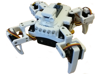
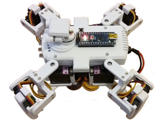
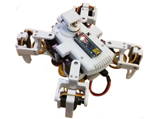
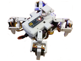
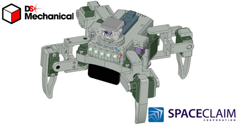
Quadruped ‘Auto’
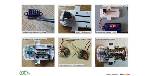
My 4th Quadruped project adds a small servo motor to rotate a laser range finder mounted in its head. This gives the robot much more freedom when roaming around autonomously. You too can make with a 3-D printer and an Arduino NANO microcontroller.
 |
|||||
| Project Overview The robot code uses a modified version of the Wii Nunchuk controller I used with my BalanceBot project. This enables it to move and steer in all four directions, as well as performing neutral turns, and special actions like bowing and waving. Have a look at the video clip on the right for a taste of what it can do and judge its potential. |
|||||
|
|
|||||
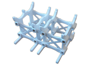
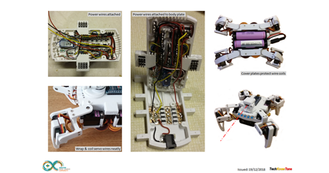
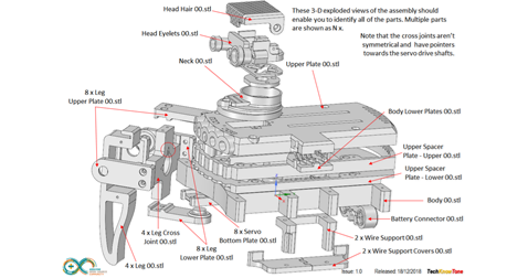
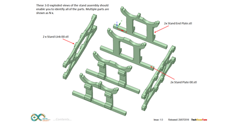
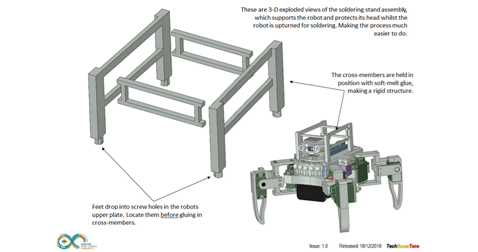
| With most forms of walking robots it is important that the design is as light as possible and well balanced in terms of its centre of gravity. If the robot is too heavy it will struggle to get off the ground and consume a lot of battery power, and if it is not balanced it will tend to rock badly when walking and turning. I decided to make this design very symmetrical, such that it can walk in all four directions with equal ease. Cable management is another thing to consider when making a small robot, as servo motor leads are deliberately long for use in model aeroplanes, so it can be quite tricky trying to effectively lose them within the design, without them appearing untidy. The design of a simple stand is also included, which is just sufficient to raise the robot a few millimetres off the ground, making it ideal for testing in a safe low power mode. |
|||||
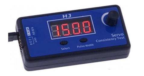
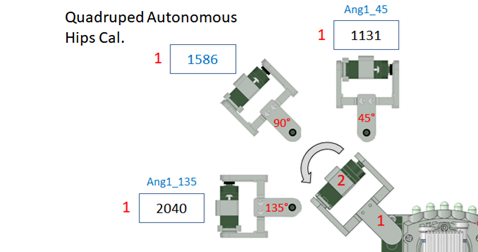
Calibration of each servo motor is key to robot performance and I’ve tried to make this straightforward for you. When building your robot you use a servo tester, which are simple to use, cheap to buy and very useful for other projects involving servo motors.
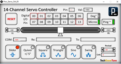
Then once you have built and wired up your robot you can complete the calibration process using a Windows based app I have written and given you for free. This tool is not only a great aid for this project, you can use it in other Arduino based projects too. You simply determine the servo angles and limits, then place them in the code as shown. Your robot will then perform in exactly the same way as mine. If you can’t run the Windows app then you can still use the servo tester for this part too.


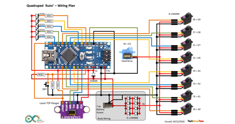
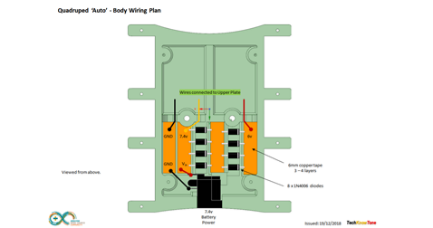
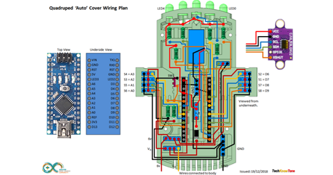
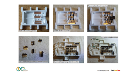
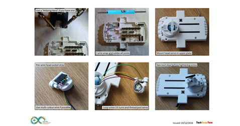
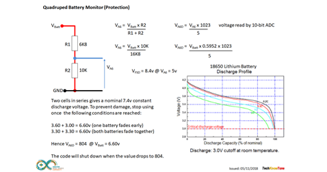
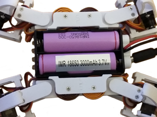
The circuit diagram is shown here on the left, with the Arduino NANO connected to the eight servo motors on the right and head servo in the centre, with 6v power being fed to the servos from a diode voltage dropping circuit. Servos will normally operate between 4.8v and 6v, but they work much better at the higher voltage. Note that this circuit assumes an input voltage of 7.5v from a power plug or 7.2v from a 2 x 18650 Lithium rechargeable battery pack. These batteries work really well but you need to avoid those with built in circuit protection as they will current trip.
To avoid running the batteries flat and damaging them, the Arduino code constantly checks the voltage and enters a safe mode should this occur. I’ve also included photos of how I wired mine up to help you with the wiring.
All of the 3-D models are provided as STL files, zipped together into one file. They can therefore be used with a slicing application of your choice, to create the g-files for use with a 3-D printer. For my project I used Slic3r which is a free download from the internet.
I’ve also provided a pdf file showing you the names of each component and the quantities you need to print of each. The design is essentially held together using M2 x 10 mm self-tapping screws, making it strong and rigid, whilst still being able to take it apart should you need to changed a component. The legs are easily removed and replaced, so you could play around with different designs, add rubber pads to offer more grip, or even attach wheels or scary spikes.

Design Files
The following files can be downloaded to help you complete this project. Each has a hyper-link and an associated description. Depending on how your web browser is configured the links will either open the files directly into the browser or offer them as downloads.
Circuit Diagram - a drawing of what is seen in the view above, plus veroboard wiring. Use it as a guide to wiring up your project. Updated: 09/12/2025.
Parts list - the things you will need and budget prices.
3-D Models - a zip file containing all of the STL files, which you can use with a slicer application.
3-D Parts - a pdf file which identifies the 3-D parts, and the quantities of each you will need to print.
Software Code - the all important Arduino .ino file which runs the project and ‘Processing’ application. See comments below on coding.
Calibration Record - shows the angles you need to determine and enter into your code to calibrate new servo motors. Updated: 09/12/2025.
Libraries
This project relies on the use of three libraries Servo.h and Wire.h, which are included in the Arduino IDE set-up. The first library is used to control the nine servo motors, whilst the second supports the I2C serial bus used to access the VL53L0X laser range finder device..
Design Notes:
The following notes will help you understand how the files in this project work or can be used in principle. Each note has a bold heading for quick reference and they are listed in alphabetical order.
.ino File - when you download this file remember to place it in a folder with the same name, otherwise the Arduino IDE will not load it and display an error message.
3-D Models - this design is based on the use of 2mm self-tapping screws and 3mm nylon countersink screws. The models have 1mm pilot holes for the self-tapping screws, and 2.5mm pilot holes for the 3mm holes which need to be threaded with a M3 tap to secure the battery box.
Calibration Record - It is essential that you undertake a calibration exercised in order to enter the correct values into your .ino file, as servo values can vary widely. Otherwise the robot will not function correctly and could even result in damage to one or more servo motors..
STL Model Files - all models are designed to be printed on a 3-D printer with a .4mm nozzle. If you use a printer with a finer nozzle, say 0.3mm, then this may result in the height of the components being slightly less than intended, but I would still expected them to work..
Need more?
If you feel that I haven’t included enough information to allow you to tackle a project of this type then send me an email explaining what you need. Or if you just want to give me some general feedback on this site, or to suggest projects what I might include which would be interesting to you, I’d be pleased to hear from you.
Page updated: 09/12/2025