
- Project
BalanceBot - A Self-balancing Robot
Having experienced the fun of riding a Segway I’ve always been impressed with self-balancing systems. In this project I’ve taken a project off the web and tweaked it to make an effective classroom demonstrator. This project is steered with a Nintendo Wii Nunchuk controller using 2.4GHz Wi-Fi and is great for explaining the principles behind self balancing control systems. Why not make one too!
 |
|||||
| Project Overview |
|||||
|
|
|||||
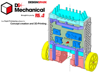
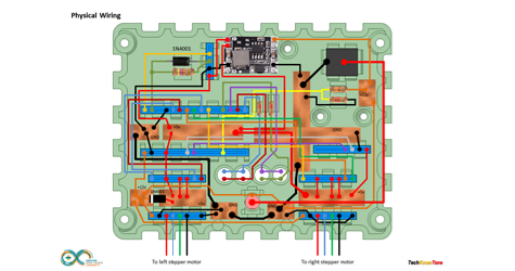
| All of the robot chassis components were produced on my 3-D printer and modelled using the free 3-D design package from RS Components, DesignSpark Mechanical. For this design I also constructed an assembly of the complete robot, to ensure that all of the parts aligned. This included simple models of the drive motors and pcb’s. Given the limitations of 3-D printing, the chassis consists of a number of parts screwed together using 3mm nylon countersunk screws. To save on filament material several of the plates are perforate, which also gives limited views of the internal wiring . Instead of using a circuit board I modelled a plate with apertures for the pcb socket strips and glued them into position using soft-melt glue. See a model overview sheet here. The 50mm drive wheels were modelled with 8 spokes and incorporate locking screws to secure them to the drive shafts. Joop’s idea of using a bicycle inner tube, to dress the wheel for added friction worked well; just trim the rubber with a modelling knife to get a good finish. You will need a 3mm tap to be able to put threads in all of the 2.5mm holes in this design. |
|||||
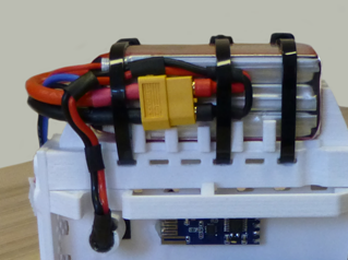
The robot is powered from a 11.1v Lipo battery pack, mounted on top of the robot. Its mass provides the inertia necessary to enable the robot to balance. The ON/OFF switch isolates the battery from the circuitry, which enters into a ‘Safe’ mode when first powered up. To make the robot active you need to place it on its back, wait for the two green LEDs to start flashing, then raise the robot into its upright position. The LED flashing rate will increase and go from green to red, then solid red as the angle increases towards it becoming active. To take the robot back into ‘Safe’ mode you need to tilt it more than 30 degrees from top centre.
When the robot receives a data from the remote transceiver connected top the Nunchuk controller it will drive and steer as demanded. Note that the robot needs to lean forwards in order to move forwards; which becomes very apparent if it is placed on a carpet, as the wheels sink into the pile and extra effort is needed to move in these conditions.
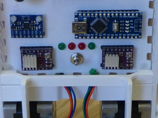
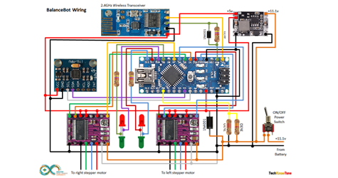
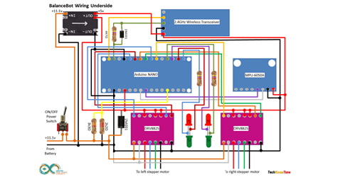
The circuit diagram for the robot is shown here on the left, with the Arduino connected to the two stepper motor drivers, the MPU 6050A 3-axis gyroscope and 2.4GHz transceiver. Initially I tried to power the pcbs from the 5v regulator on the NANO, but this did not work, resulting in a dead NANO and gyro! So like Joop I then incorporated a separate 5v regulator, which worked fine. This was therefore mounted behind the front panel, and is not visible at the front.
As I was using a NANO clone the transceiver Rx signal was not strong enough, after passing through the 4k7 ohm resistor, to be detected by the NANO. To overcome this it was necessary to place a 1N4001 diode across the resistor to enable it to pull the signal low enough.
Arduino digital pins aren’t capable of driving stepper motors directly, so we achieve this using two DRV8825 driver pcbs, commonly used in 3-D printers, which generate the necessary waveforms for the motors. Note that you will need to calibrate these driver pcbs to avoid excess current being passed through the motors. Start with the potentiometers turned fully clockwise, and slowly turn counter-clockwise whilst monitoring the battery current. Only connect one motor at a time so as not to confuse the readings.
By default these drivers are set to about 1 Amp, but you only need about 100-150 mA in practise. So doing this will not only put less stress on your motors, it will also ensure that the robot can run for the maximum period of time on one battery charge..

Design Files
The following files can be downloaded to help you complete this project. Each has a hyper-link and an associated description. Depending on how your web browser is configured the links will either open the files directly into your browser or offer them as downloads. An update has now been included which provides files which enable you to construct the detachable head, seen in the above video.
Circuit Diagram - a drawing of what is seen in the view above. Use it as a guide to wiring up your project.
Parts List- the things you will need and budget prices.
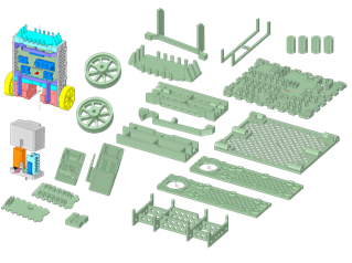
3-D Parts - images showing you what the 3-D parts look like. To be expanded to include the ‘head’ shortly.
3-D Models - a zip file containing all of the STL files, which you can use with a slicer application.
Software Code - the all important Arduino .ino files. Several files for the robot, Nunchuk remote and PID controller app - Updated 28/01/2023.
PID Controller - a pdf explaining the use of a PID controller app included in this update - New.
3-D Parts Update - a pdf explaining how the robot head is constructed from parts included in the 3-D Models Update.
3-D Models Update - a zip file containing STL files of the head components and the latest version of code.
Safe Modes - a video showing the sequence of taking the robot into self-balance mode. - New.
Calibration - a pdf explaining how to record and remove MPU6050 offsets, to improve sensor accuracy - New.
Libraries
This project relies on the use of two libraries, Wire.h and SoftwareSerial.h which is included in the IDE set-up. The Wire.h library provides the interface for I2C devices used in the robot and the controller. You have two in this project, one being the MPU6050 3-axis Gyro and the second being the Wii Nunchuk controller. See notes below regarding the need to calibrate the stepper motor drivers and the balance point of your robot. SoftwareSerial.h is used in the Nunchuk controller code to provide a feed-through function for use with the IDE serial monitor.
Design Notes:
The following notes will help you understand how the files in this project work or can be used in principle. Each note has a bold heading for quick reference and they are listed in alphabetical order.
.ino File - the zip file contains several folders, which in turn contain the source code files. Therefore you will need to unzip it to use it.
3-D Models - the constructions of this design is based on the use of 3mm nylon countersink screws, with the exception of the metal screws used to mount the stepper motors. This leads to a very clean shake-proof solution. Metal screws are used to mount the stepper motors and lock the wheels onto the motor shafts. You will need a 2.5mm drill and 3mm tap to thread some of the holes.
Calibration - You will want to calibrate the stepper motor driver currents, to prevent wasting power and overheating. Start with the potentiometers turned fully clockwise (minimum current) then turn slowly counter-clockwise to increase the current. I set mine to 150 mA for each motor. You will also need to set the calibration value for the accelerometer to determine the vertical position. Ensure that the MPU6050 board is parallel with the line of the robots body. Then find the balancing point of the robot and get the reading from the serial monitor. Switches in the code allow you to do this statically, and the feed-through function of the remote control unit can help you obtain dynamic readings from the robot when it is on the move.
Demo - as the role of this robot is to act as a demonstrator, it is possible to switch OFF the gains in the PID controller using prolonged presses of the ‘C’ button on the Nunchuk controller. This enables you to demonstrate the effects of the proportional, integral and derivative terms of the PID controller.
Need more?
If you feel that I haven’t included enough information to allow you to tackle a project of this type then send me an email explaining what you need. Or if you just want to give me some general feedback on this site, or to suggest projects what I might include which would be interesting to you, I’d be pleased to hear from you.
Page updated: 28/01/2023