
- Project
PixyBot2
We are now seeing intelligent sensors in many applications, like self-driving vehicles. Here I have used an AI camera, known as a Pixy2 to create a robot which runs on a 4x4 chassis, driven by mecanum wheels. The camera is designed to work with microcontrollers like Arduino and ESP32, so elements of this project may be of interest to you in other applications.
Project Overview
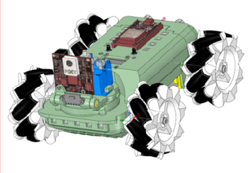
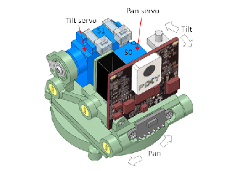
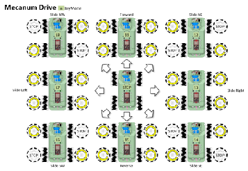
This robot uses 4 DC motors to drive mecanum wheels, which enable it to be driven in any direction. The Pixy2 camera is mounted on a pan & tilt mechanism, giving it plenty of freedom to track objects that are presented to it. Attached to the base of the camera is laser range finder, enabling it to measure distance in millimetres. The wheel drive shafts have optical slot encoders which allow the robot to measure how far it has travelled or turned. The ESP32 micro can be connected to a Wi-Fi transceiver, enabling it to be controlled remotely using a Wii Nunchuk controller, and to send data over the air to be displayed on a PC screen..
Click on the image to the right to see the robot being put through its paces. The OLED display contents can be sent to a Windows application, over WiFi, to give a large screen view..

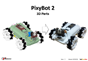
This design was created using a 3-D modeller and printer, to ensure that the assembly goes together with ease. The released design benefits from a range of improvements that were determined from building the first prototype. You will learn from the documentation how this design was put together and wired up.
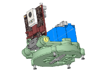
The body is essentially made in two halves, held together by small screws. This makes the overall assembly easier to build and offers a degree of maintainability. The pan mounting has graduations built into it to make the calibration process simpler to achieve. This element of the design could be used as a stand-alone pan & tilt solution for another project, albeit the Pixy2 makers can provide a kit for this if needed.
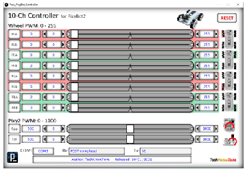
In order to accurately calibrate the Pan & Tilt servo, and to adjust the PWM values needed to drive the 4 DC motors, I have provided a custom Windows app, which makes this task much easier. It also allows you to play around with the motor drives, to gain a better understanding of how they work. The code also contains control algorithms, making it easy to drive and position the camera.
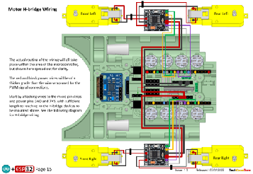
The nylon gears used within the wheel motors, combined with the inertia associated with the weight of the robot, means that a large starting torque is required to overcome the initial friction, but once the robot is moving, much less torque is required. This characteristic is addressed by superimposing a low frequency (30 Hz) dither signal on top of the motor demand value, which effectively vibrates the wheels into action. This presents a much lower starting torque, and makes it much easier to control.


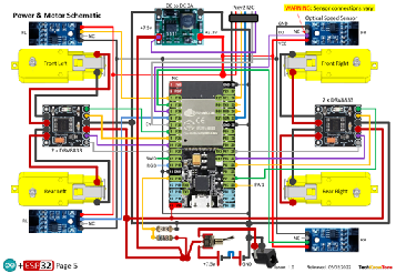
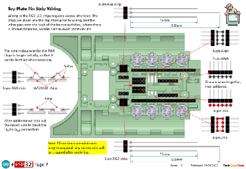
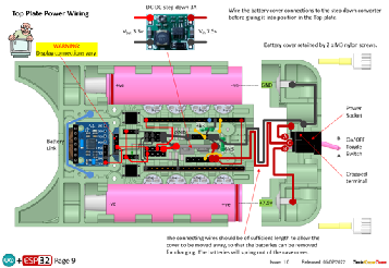
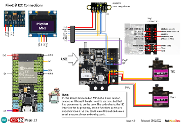
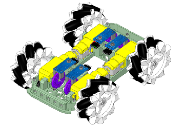
The circuit diagram is shown here on the left, with the ESP32 connected to the 4 DC motors, with 3v3 power being derived from a DC-DC step down module, to power the RGB LEDs and most of the attached circuitry. Because of the number of PWM signals and slot encoders used in this design, we use most of the pins on the ESP32. I initially intended to use interrupts to capture changes in the wheel slot encoders, but as this proved not to be possible, I used the second core of the ESP32 to pole these sensors on a regular basis.; which works fine on slow speeds where automated movement requires some precision.
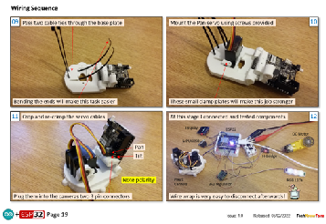
In construction I use wire wrap technology to make the process easier and more reliable. There is however an initial outlay in buying the wrapping tool and spools of wire. One benefit of this approach is that you can run and test your design before soldering the connections for improved reliability. Any errors can therefore be easily addressed during construction.
All of the 3-D models are provided as STL files, zipped together into one file. They can therefore be used with a slicing application of your choice, to create the g-code files for use with a 3-D printer. For my project I used PrusaSlicer, which is a free download from the internet. I’ve also included a simple stand, which clips onto the base of the PixyBot2 for testing or demonstration.
The project is meant to be built in two parts, one being the PixyBot2 robot and the other being the Wii wireless transceiver box (optional). You will need to download models and instructions for that project from this page here. Whilst the PixyBot2 does operate in several stand-alone modes, without doubt the use of the Wii Nunchuk and wireless link are great additions to this project. One feature is that you can send the contents of the OLED display over the air to a PC screen or large monitor. The wireless project is also used as a common component with several other projects, and is likely to be needed for others in the future. So it is well worth considering.
Design Files
The following files can be downloaded to help you complete this project. Each has a hyper-link and an associated description. Depending on how your web browser is configured the links will either open the files directly into the browser or offer them as downloads.
Circuit Diagram - a detailed pdf of what is seen in the view above. Use it as a step by step guide to wiring up your project. Updated: 26/11/2025.
Parts list - the things you will need and budget prices. The Wii Nunchuk WiFi controller is not included; see separate project here.
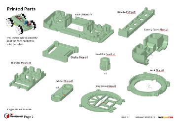
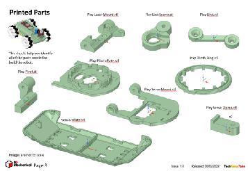
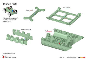
3-D Models - a zip file containing all of the STL files, which you can use with a slicer application.
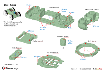
3-D Parts - a pdf file which identifies the 3-D parts, their critical features and how to prepare them for assembly
Software - the all important code, .ino files for HexBot2 and WiFi transceiver, plus two ‘Processing’ applications. Updated: vR2. 2024/07/16.
Calibration - shows the critical angles you need to determine and enter into your code to calibrate your servo motors. Updated: 26/11/2025.
Demo Functions - a pdf explaining the functions available with buttons and when using a Wii Classic controller.
Libraries
This project relies on the use of nine libraries, <Arduino.h>, <HardwareSerial.h>, <ESP32Servo.h>, <Wire.h>, "SSD1306Wire.h", <FastLED.h>, "SparkFun_VL53L1X.h”,<esp_now.h>, <WiFi.h>, which need to be included in the IDE set-up, in order for the .ino code to compile correctly. If you haven’t used an ESP32 before with the Arduino IDE, then you will need to install the board libraries too. There are several articles on the web that explain this process.
Design Notes:
The following notes will help you understand how the files in this project work or can be used in principle. Each note has a bold heading for quick reference and they are listed in alphabetical order.
.ino File - the software .zip file contains three folders: PixyBot2_00, Proc_OLED_Mirror, and Proc_PixyBot_Controller, which in turn contain several files. These are all to be extracted and retained within the same folders, of those named. If you are wondering why there are several .ino files, it is because I use the tabbed interface within the Arduino IDE, and for each tab there is a corresponding .ino file. The OLED Mirror and PixyBot Controller apps are compiled Java versions, which will run without installation, once decompressed from the zip file into a normal folder. They were both written in C++ using the ‘Processing’ development environment. The OLED Mirror app works either directly from the PixyBot2 being connected to a USB serial port, if a Wii Transceiver is connected to the USB serial port and in turn connected to the PixyBot2 over the Wi-Fi link.
3-D Models - this design is based on the use of 2x10 mm steel countersink screws. The pdf files provided should give you sufficient information to identify the parts and indicates the quantity of each to be printed.
Calibration - It is essential that you undertake a calibration exercise, in order to enter the correct values into your .ino file, as servo values can vary widely. The more accurately you perform this important process, the better the pan and tilt performance of the robot.
Serial Port - is used in this design convey readings and commands to the HexBot2, and for general debugging purposes. Being able to see the servo values being applied to each servo is very useful and essential to calibration. If you also build the WiFi Transceiver project you will be able to connect that unit to your PC via USB and communicate wirelessly with the HexBot2.
STL Model Files - use these with your favourite slicer application. In the 3D Parts pdf document I have indicated the size of pilot holes needed for the screws..
Need more?
If you feel that I haven’t included enough information to allow you to tackle a project of this type then send me an email explaining what you need. Or if you just want to give me some general feedback on this site, or to suggest projects what I might include which would be interesting to you, I’d be pleased to hear from you.
Page updated: 26/11/2025