
- Project
MATRIX+ - Animation Editor
Building on the success of my previous MATRIX project, I’ve now updated the system, adding a lot of useful features. The app now has a built in simulator, so you don’t need any hardware to create and try out you animations, and the micro controller now has two outputs, so it can drive large panels at a higher frame rate, or drive two, with one being the clone of the other. Check it out now by watching the video!
Project Overview
A lot was learnt from the original project, which was created in support of a local school wanting to build several display panels for a light show, at the 2021 Lumiere festival held in Durham city centre. With the MATRIX+ Windows app ,you can create numerous images and slogans, which you then combine into animation sequences using a script based editor. With the new, built-in simulator you can instantly test your visual effects, before saving them to the microSD card on the controller. Once loaded you don’t need a PC to run them, and multiple animations can be strung together in a long sequence. User interaction, with switches/touch panels, is now provided too.
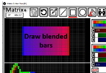
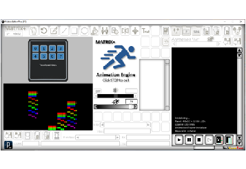
Click on the image to the right, to see examples of what can easily be created using the MATRIX+ app. These are also included with the download files to help you get started.

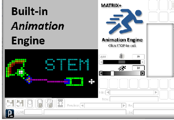
There are a lot of improvements included in MATRIX+, as shown briefly here. If the controller is not connected to the app when you press the ‘Play’ button, your animation will be simulated within the app, as it would if the LED controller and panels were connected. This means that you can try out your ideas, and get a feel for using the app, without needing to invest in hardware. Once you are happy with what you have created, you can then build the controller and panels with confidence.
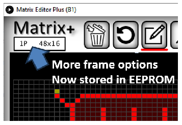
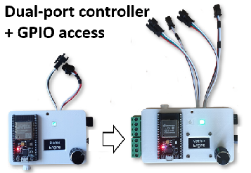
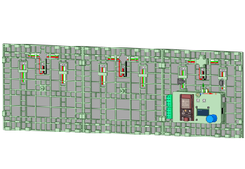
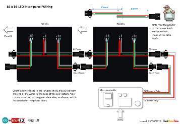
The micro controller now has two data output, which means that you can sub-divide a large panel into two halves, and effectively drive them at twice the speed of a single panel. Or alternatively you can use the second output to drive a identical clone of the first. There are also more options for panel configurations, from a single 16x16 panel to a maximum of 48x128 (that’s 6144 pixels!).
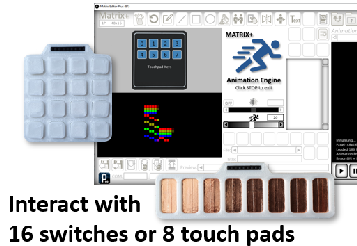
External switches can also be read within your animation script, making your animations interactive!.
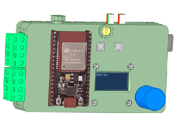
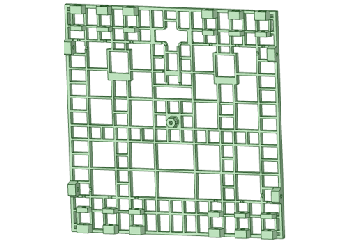
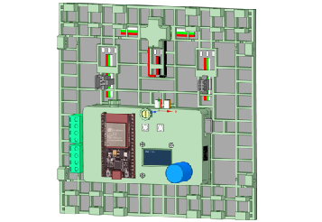
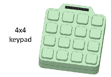
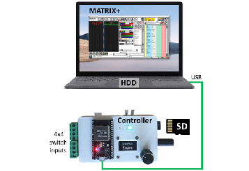
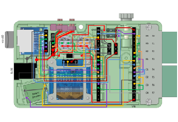
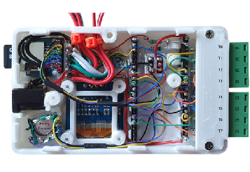
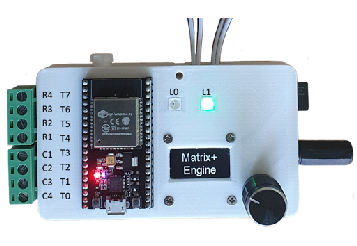
The design was created using a 3-D modeller and printer, to ensure that the assembly goes together with ease. The ESP32 microcontroller is housed in a small box, along with the 64x128 OLED display, a rotary encoder and a removable microSD card. This box mounts directly onto the back of the first LED matrix supporting frames, and they in turn connect together to make a larger display. The flexible 16x16 LED panels are glued to the supporting frames, which act as stiffeners.
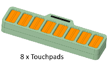
The panels are grouped together using M3 screws and interlocking bars, and short legs can be fitted in the corners, so that they can be rotated outwards to hold the display panel in a vertical plane. But if you wish the LED panels could just as easily be mounted on a single sheet a plywood, with holes to allow the wires to come through to the back; or embedded in a table top along with touchpad switches. Get creative.
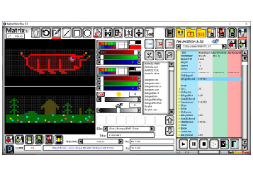
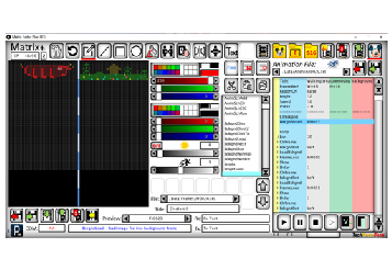
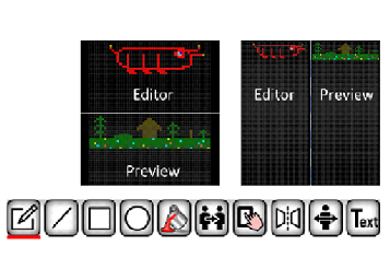
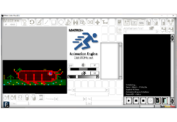
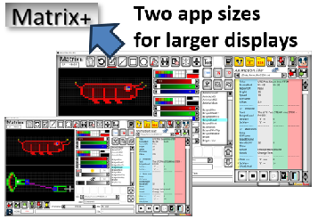
The Matrix app was developed in ‘Processing’ an environment very similar to the Arduino IDE, and you can download the Java executable file from a link below; which runs on a PC without the need to be installed. The left-hand graphics editor supports multiple panel formats, and provides a range of drawing tools like freestyle pen, line, box and circle, as well as more sophisticated options like flood fill, cloning, moving, mirroring and flipping areas, as well as a simple text drawing mode.
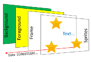
The right-hand side is the animation script editor, which is like a simple programming language, with commands like ‘Bright’ to set the LED brightness, and ‘Speed’ to set the animation frame rate Just like conventional animation, the script supports multiple planes, used to build up the output image, and special functions like scrolling text and sprites. The editor is a ‘click’ to select and modify tool, with the only need for typing being to enter text for comments and display purposes. There is a simple help system too, which details the controls currently under the mouse pointer..
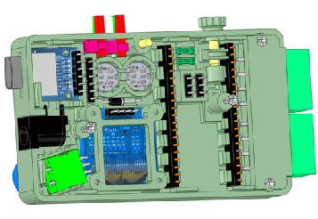
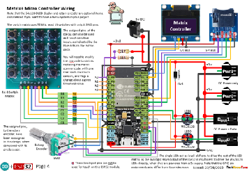
The circuit diagram for the control box is shown here on the left, with the ESP32 connected to the microSD card and display, as well as a rotary encoder, to provide a simple menu system on the display. As the ESP32 board runs at 3.3 volts, and the WS2812B LEDs run at 5 volts, there is an issue of incompatibility which has to be resolved with a level shifter circuit. This is solved by using single WS2812B LEDs in the controller, powered from the 5 volt rail, but through diodes. This intermediate voltage supply ensures that the ESP32 can drive this LED, and it in turn can drive the first LED in the LED matrix. Problem solved reliably!
In construction I use wire wrap technology, to make the process much easier and more reliable, and you can even test your solution before needing to solder it. There is however an initial outlay in buying the wrapping tool and spools of wire, but it’s well worth it for this and other projects..
Design Files
The following files can be downloaded to help you complete this project. Each has a hyper-link and an associated description. Depending on how your web browser is configured the links will either open the files directly into the browser, or offer them as downloads.
Circuit Diagram - a detailed pdf of what is seen in the views above. Use it as a step by step guide to wiring up your project.
Parts list - the things you will need, and indicative budget prices.
3-D Models - a zip file containing all of the STL files, which you can use with a slicer application for 3-D printing.
3-D Parts - a pdf file which identifies the 3-D parts, and to prepare them for assembly
Controller Code - the all important .ino code for the Matrix+ microcontroller. See comments below on coding
Matrix+ app - the Matrix+ application, compiled into 32-bit and 64-bit Java. You will need the Java run-time component installed in Windows.
Quick Guide - introduces the Matrix Editor and outlines its many features
Command Reference - a pdf file containing essential descriptions of each command used in the script editor.
Libraries
This project relies on the use of nine libraries, <Arduino.h>, <HardwareSerial.h>,, <Wire.h>, "SSD1306Wire.h", <FastLED.h>, “FS.h”,”SD.h”,”SPI.h”, and <stdlib.h>, which need to be included in the IDE set-up, in order for the .ino code to compile correctly. If you haven’t used an ESP32 before with the Arduino IDE, then you will need to install the board libraries too. There are several articles on the web that explain this process. I would recommend this one by Random Nerd Tutorials.
Design Notes:
The following notes will help you understand how the files in this project work or can be used in principle. Each note has a bold heading for quick reference and they are listed in alphabetical order.
Controller Code - the software .zip file contains a folder: Panel_Plus_R1, which in turn contains several .ino files. These are all to be extracted and retained within a folder of the same name. If you are wondering why there are several .ino files, it is because I use the tabbed interface within the Arduino IDE, and for each tab there is a corresponding .ino file. All files need to be present in the root folder for the code to compile successfully in the Arduino IDE.
Matrix+ app - the software .zip file contains a root folder: Matrix_Editor_R1, which in turn contains sub-folders and files. You will see that there is a 32-bit version and a 64-bit version. Providing that you have Java run-time installed in Windows, one or the other should run, depending on the Java version. Note that alongside the executable file there are two sub-folders, data and lib. You can ignore lib folder, which is needed by the app to run, but the data folder is where your images and animations will be stored. Refer to the Quick Guide for more information on this. There are also picture .png files, which are used by the Matrix+ app and they should not be modified.
3-D Models - THe .zip file contains two folders, one for the parts used in creating the controller and framing the 16x16 panels, and the other folder contains parts for creating switch boxes. The pdf files provided should give you sufficient information to identify the .stl parts and indicates the quantity of each to be printed. As the ESP32 can come in different board sizes I have included two cases to accommodate whichever part you have purchased. There is a 30 mm M3 nylon screw which passes through the case to hold it onto the back of the first LED panel, but you may choose to simply mount the LED 16x16 matrices onto a piece of plywood, if that suits you better.
Serial Port - is used in this design connect the ESP32 controller to the Matrix application, running on your PC. The baud rate used is 500,000 bps, as a lot of data may need to be transferred to the controller in the form of graphics images. Clicking on the serial COM port field in the application causes it to connect to the controller. A right-click will cause it to disconnect, which is useful if you are using the Arduino IDE serial port or programming in parallel.
STL Model Files - use these with your favourite slicer application. In the 3D Parts pdf document I have indicated the size of pilot holes needed for the screws..
Need more?
If you feel that I haven’t included enough information to allow you to tackle a project of this type then send me an email explaining what you need. Or if you just want to give me some general feedback on this site, or to suggest projects what I might include which would be interesting to you, I’d be pleased to hear from you.
Page updated: 01/10/2023