
- Project
LightBot
The efficiency of solar panels has risen dramatically over recent years, and they are now very affordable. It’s important however to ensure that they are always pointing towards the light source to gain the most from them. This project looks are a light tracking robot, to which you could attach a small panel, or make just to have fun with.
Project Overview
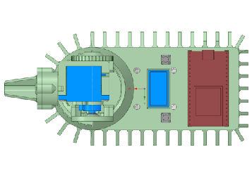
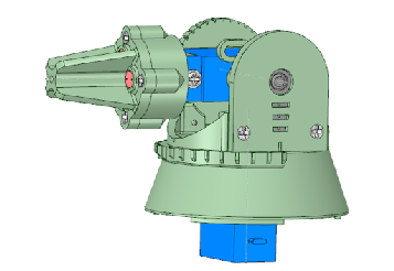
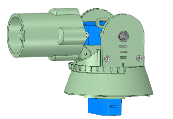
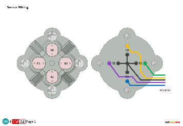
This robot uses 4 independent light sensitive resistors, mounted on a pan and tilt head, which is driven by 2 servo motors. The protruding shape of the head is such that parallel light coming towards it easily casts shadows on one or more sensors. The micro reads each sensor in turn at a high rate and can sense any imbalance in the light levels being received. This imbalance, when it occurs, is then used by the code to drive the pan and tilt servos, so as to bring them back into balance. Once calibrated the robot appears to have excellent characteristics for sensing illumination bright spots, and tracking things like moving torch light quite quickly.
Click on the image to the right to see the robot being put through its paces. The OLED display contents can be sent to a Windows application, over WiFi, to give a large screen view.

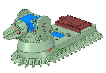
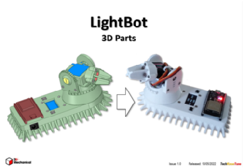
This design was created using a 3-D modeller and printer, to ensure that the assembly goes together with ease. The released design benefits from a range of improvements that were determined from building the first prototype. You will learn from the documentation how this design was put together and wired up.
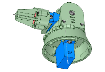
The main body is essentially made in two halves, held together by small screws. This makes the overall assembly easier to build and offers a degree of maintainability. The pan mounting has graduations built into it to make the calibration process for the two servos simpler to achieve. This element of the design could be used as a stand-alone pan & tilt solution for another project.
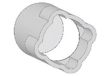
In order to accurately calibrate the 4 light sensitive resistors, I designed a tube which fitted over the head. The inside of the tube was painted black, so as to reduce any external light hitting the sides of the tube, and I glued a piece of paper over the end of the tube to diffuse any light shone onto it. I could then use a external light source, like a torch, to illuminate the end of the tube and take measurements from all four sensors.
There is a calibration mode built into the code to assist with this process. It moves the head to the vertical position and presents all 4 readings on the display, averaged over 5 seconds, plus the average of all of them. With this method you can use these readings in map() functions to effectively offset the raw value received from the sensor. As the full scale on the ESP32’s ADC is 4095, I took eight readings, going from dark to bright light, at intervals of 500. The end result worked really well.
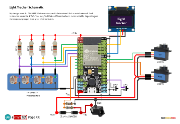
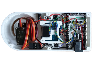
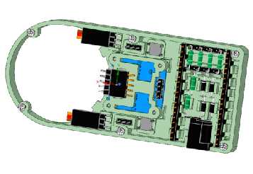
The circuit diagram is shown here on the left, with the ESP32 connected to the 4 light sensitive resistors, and to the OLED display using the I2C interface. Whilst the pan and tilt servo motors derive their supply voltage from a simple diode voltage dropper. A voltage divider is used to sample the input supply voltage, with code providing continuous battery health monitoring.
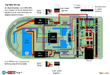
In construction I use wire wrap technology to make the process easier and more reliable. There is however an initial outlay in buying the wrapping tool and spools of wire. One benefit of this approach is that you can run and test your design before soldering the connections for improved reliability. Any errors can therefore be easily addressed during construction.
Give the variations found with light sensitive resistors I would advise that you purchase more than needed, then select four which provide very similar readings.
All of the 3-D models are provided as STL files, zipped together into one file. They can therefore be used with a slicing application of your choice, to create the g-code files for use with a 3-D printer. For my project I used PrusaSlicer, which is a free download from the internet. I’ve also included a simple stand, which clips onto the base of the PixyBot2 for testing or demonstration.
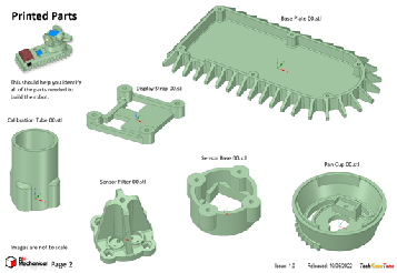
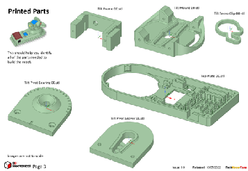
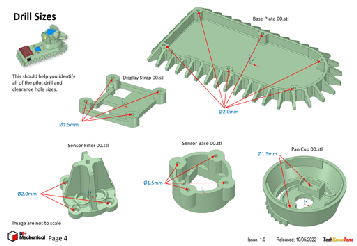
The project is built in two parts, one being the servo Pan & Tilt mechanism, with the light sensors, and the other being the main body. The mounting cup of the Pan swivel is graduated, as is the Tilt bearing plate, so as to make calibration of the two servos much easier. Information presented on the 64x128 OLED display can be sent wirelessly to a PC using the Wii Wireless Controller project, if you wish to build that and use it. The 3D Parts pdf file helps you identify each part by name, and also shows you what drills to use as pilot holes for the screws.
Design Files
The following files can be downloaded to help you complete this project. Each has a hyper-link and an associated description. Depending on how your web browser is configured the links will either open the files directly into the browser or offer them as downloads.
Circuit Diagram - a detailed pdf of what is seen in the view above. Use it as a step by step guide to wiring up your project.
Parts list - the things you will need and budget prices. The Wii Nunchuk WiFi controller is not included; see separate project here.
3-D Models - a zip file containing all of the STL files, which you can use with a slicer application.
3-D Parts - a pdf file which identifies the 3-D parts, their critical features and how to prepare them for assembly
Software - the all important code, .ino files for the LightBot, plus two ‘Processing’ applications. Update: vR2, 2024/07/14.
Calibration - shows the critical angles you need to determine and enter into your code to calibrate your servo motors - Updated Oct’22.
Libraries
This project relies on the use of seven libraries, <Arduino.h>, <HardwareSerial.h>, <ESP32Servo.h>, <Wire.h>, "SSD1306Wire.h",<esp_now.h>, <WiFi.h>, which need to be included in the IDE set-up, in order for the .ino code to compile correctly. If you haven’t used an ESP32 before with the Arduino IDE, then you will need to install the board libraries too. There are several articles on the web that explain this process.
Design Notes:
The following notes will help you understand how the files in this project work or can be used in principle. Each note has a bold heading for quick reference and they are listed in alphabetical order.
.ino File - the software .zip file contains three folders: Light_Tracker, Proc_16Ch_Controller_06, and Proc_Joystick_Controller, which in turn contain several files. These are all to be extracted and retained within the same folders, of those named. If you are wondering why there are several .ino files, it is because I use the tabbed interface within the Arduino IDE, and for each tab there is a corresponding .ino file. The Proc_16Ch_Controller_06 and Proc_Joystick_Controller apps are compiled into Java versions, which will run without installation on Windows 10, once decompressed from the zip file into a normal folder. They were all written in C++ using the ‘Processing’ development environment.
3-D Models - this design is based on the use of 2x10 mm steel countersink screws. The pdf files provided should give you sufficient information to identify the parts and indicates the quantity of each to be printed.
Calibration - It is essential that you undertake a calibration exercise, in order to enter the correct values into your .ino file, as servo values can vary widely. The more accurately you perform this important process, the better the pan and tilt performance of the robot.
Serial Port - is used in this design convey readings and commands to the LightBot, and for general debugging purposes. Being able to see the servo values being applied to each servo is very useful and essential to calibration. If you also build the WiFi Transceiver project you will be able to connect that unit to your PC via USB and communicate wirelessly with the HexBot2.
STL Model Files - use these with your favourite slicer application. In the 3D Parts pdf document I have indicated the size of pilot holes needed for the screws..
Need more?
If you feel that I haven’t included enough information to allow you to tackle a project of this type then send me an email explaining what you need. Or if you just want to give me some general feedback on this site, or to suggest projects what I might include which would be interesting to you, I’d be pleased to hear from you.
Page updated: 12/05/2022