
- Project
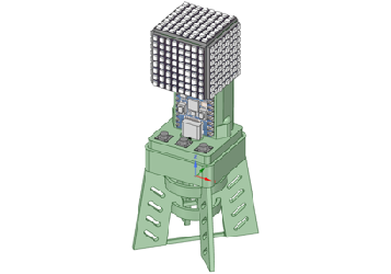
Cube 8x8x5 HD
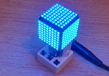
This is a compact high density version of the light cube I made back in 2021. It uses these amazing DotStar LED panels, and despite its size, I was able to include all of the sensors and features of the original design. It also runs the full set of animations, and more!
Project Overview
This project uses the ESP32C3 single-core micro to develop a wide range of animated light patterns on five faces of a cube, using DotStar RGB LEDs configured as small 8x8 panels. Built into this cube is a 3-axis motion sensor, a microphone and an ambient light sensor, so that it can respond to changes in it’s environment. The code I have provided contains a library of graphics functions, which can be combined in interesting ways to develop a wide range of lighting effects. The cube can also be used as a desk lamp and to provide mood lighting of any colour you choose.
Watch the video on the right to see how they perform, and an insight into the technologies mentioned above.


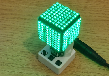
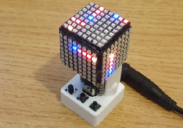
Using the 3 button switches at the base of the cube you can simply switch it ON or OFF, or select a specific pattern. The code stores your latest choice, so that it returns to that mode when it is switched ON again, or when power is resumed. Most of the patterns are animated in some way, mainly by sounds picked up via the microphone, or via the motion sensor.
Whilst we are driving 320 LEDs in this project, the data rate is high enough to support frame rates in excess of 30 fps, so good animation effects can be a achieved. You can also vary the frame rate dynamically, which in turn speeds up or slows down the animation.
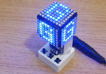
The graphics library (Gfx) provided enables you to draw boxes and lines, copy side faces, rows and columns, rotate faces and even draw 8x8 characters at any point on a face, in any colour. And it is relatively easy to add more functions, depending on your C++ coding skills.
The code runs in multi-tasking modes, which enable it to respond to button switch presses and sensor readings, whilst driving the 320 RGB array. It uses the FastLED library for that.
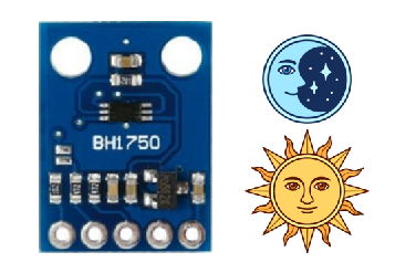
The ambient light sensor enables the cube to be dimmed down in low light conditions, so that it does not appear to be too bright, just like an LED alarm clock.
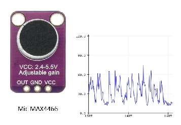
The DC offset analogue signal from the microphone is sampled at a high rate, then subjected to filtering to remove the offset, make it unipolar, and apply squelch and peak detection functions.
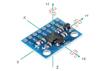
The 3-axis motion sensor provides raw and filtered acceleration and gyroscopic rotation data. So the code can detect precise movements, and feed the data into animations.

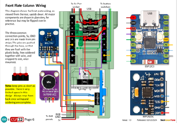

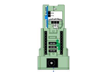
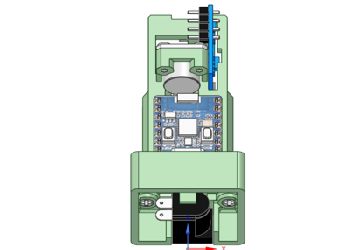
The circuit diagram is shown here on the left, with the ESP32C3 micro connected to the microphone on the left, and the light and motion sensors at the top. The LED cube takes its power from the 5v feed, and is connected to the micro for the data. With these DotStar panels then appear to work well from a 3v3 logic output, so there is no need for a level-shifting LED, as in the larger panel.
The 3 button switches are connected to individual inputs, which are configured as pull-up resistors to reduce the component count. When you press a button switch the code in the micro produces a colour in the single LED built into the micro, as confirmation.
Note that LEDs are only 40% efficient, so at high brightness these panels consume a large current and they will heat up. If you wish to run them at high brightness levels, you should predict the current drawn, and limit the brightness in code, so as to avoid panel failure due to overheating.
All of the 3-D models are provided as STL files, zipped together into one compressed file. They can therefore be used with a slicing application of your choice, to create the G-code files for use with a 3-D printer. For my project I used PrusaSlicer, which is a free download from the internet, but there are many other free applications to choose from. I just think that PrusaSlicer is one of the best.
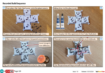
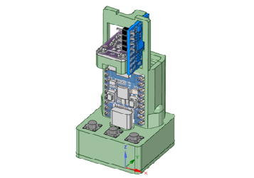
The cube is assembled from a single flat plate, that folds up to form the cube, once the 8x8 panels have been glued to it. Space is very limited in this design, so some components are glued into position, like the ESP32C3 micro; as sockets would impact on the depth of the case.
The cube is powered from an external DC wall adapter working at 5 volts. I chose a 3 Amp unit, which provides more than enough light from the LEDs, but for maximum brightness you would need a supply in the order of 10 Amps, and the cube would get very hot indeed.


Design Files
The following files can be downloaded to help you complete this project. Each has a hyper-link and an associated description. Depending on how your web browser is configured the links will either open the files directly into the browser or offer them as downloads.
Circuit Diagrams - a series of diagrams, followed by assembly instructions Updated: 29/01/2025.
Parts List - the things you will need and budget prices.
3-D Models - a zip file containing all of the STL files, which you can use with a slicer application Updated: 21/01/2025.
3-D Parts - a pdf file which identifies the 3-D parts, their critical features and how to prepare them for assembly Updated: 21/01/2025.
Software Code - the all important ESP32 .ino files which contain the cubes code. See comments below on coding. Updated: vR1. 30/01/2025.
Functions Card - a drawing explaining the use of the 3 button switches.
Libraries
This project relies on the use of four libraries, Wire.h, FastLED.h, BH1750FVI.h, EEPROM.h which need to be included in the IDE set-up. If you haven’t used an ESP32C3 before with the Arduino IDE, then you will need to install the board libraries too. There are several articles on the web that explain this process.
Design Notes:
The following notes will help you understand how the files in this project work or can be used in principle. Each note has a bold heading for quick reference and they are listed in alphabetical order.
.ino File - the .zip file contains the source folder, which in turn contains several .ino files. These are all to be extracted and retained within the same folder, of that name. If you are wondering why there are several .ino files, it is because I use the tabbed interface within the Arduino IDE, and for each tab there is a corresponding .ino file.
3-D Models - this design is based on the use of epoxy adhesive and 2x10mm steel countersink screws. The 3-D Parts document identifies the parts and shows what pilot hole sizes are required.
Serial Port - is used in this design convey readings and commands over the Arduino IDE Serial Monitor, and for general debugging purposes. Being able to adjust animation values being applied is very useful, and essential in optimising your creations.
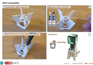
STL Model Files - The files include a stand for the cube, and a frame in which the LED panels are held during wiring..
Need more?
If you feel that I haven’t included enough information to allow you to tackle a project of this type then send me an email explaining what you need. Or if you just want to give me some general feedback on this site, or to suggest projects what I might include which would be interesting to you, I’d be pleased to hear from you.
Page updated: 30/01/2025