
- Project
BallBot 3x3 - A Self-balancing Robot
Given the success of my previous BalanceBot project I wanted to raise the bar and develop a more advanced robot which can balance on a ball. Whilst this challenge has proven to be more difficult than I thought, I now have a demonstrator that is great for explaining complex self balancing principles. Why not have a go yourself.
Project Overview
To balance on a ball you need to be able to move it in any direction, to remain on top of it. This project uses robot omni wheels, which can be driven in one direction whilst rolling freely at right-angles. Three wheels angled at 120° to each other can therefore provide movement in any direction. Gyroscopes and accelerometers are used to sense the slightest imbalance, which triggers the control system to drive each motor to respond to the error. The 2.4 GHz Wi-Fi link is used with a Wii Nunchuk to control the robot, and to convey dynamic data which can be displayed as graphs on a PC screen for detailed analysis, whilst the robot is moving. Click the image on the right to watch a video of my BallBot in action-->

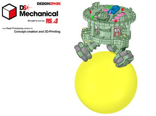
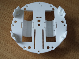

All of the robot chassis components were produced on my 3-D printer and modelled using the free 3-D design package from RS Components, DesignSpark Mechanical. For this design I also constructed an assembly of the complete robot, to ensure that all of the parts aligned. This included simple models of all bought components like the motors and H-bridge driver pcb’s. Given the limitations of 3-D printing, the chassis consists of a number of parts screwed together using nylon countersunk screws. The top plate has compartments for the two batteries and apertures for socket strips to take the micro and Wi-Fi transceiver.
The lower body consists of two plates to provide a strong platform on which to mount the motorized legs, which are adjustable to suit a range of ball sizes. You will need small drills and metric taps to be able to put threads in all of the holes in this design.
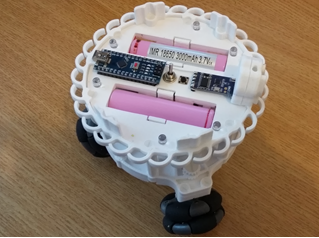
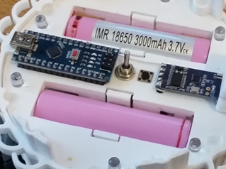
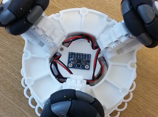
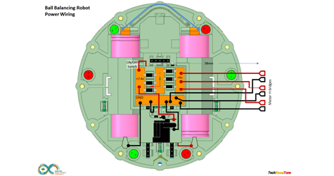
The robot is powered from two 18650 Lithium batteries, delivering 7.4v to the system. An On/OFF switch is mounted in the centre, adjacent to a push buton switch which gives you the ability to select modes of operation. On power-up the robot should be on a level surface, as it immediately enters into a calibration routine, which trims out any offsets in the accelerometers and removes gyro drift.
Red and green LEDs are also mounted in the top face, which provide moving patterns of light to indicate what the robot is doing and to indicate when the robot is being moved towards vertical as its self-balancing trigger point. The graphing app, I mentioned earlier, is also used to tune the robots PID controller using sliders presented on a PC screen. These adjustments are sent to the robot over the Wi-Fi link and their effect can be seen instantly. So if you choose a ball which is larger than the one I have used, you should still be able to find sets that achieve a stable self-balancing condition.

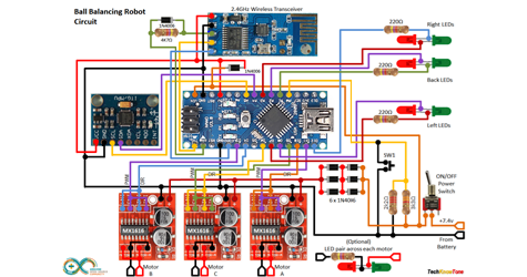
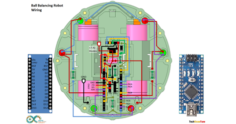
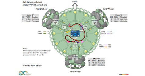

The circuit diagram for the robot is shown here on the left, with the Arduino connected to the three H-bridge drivers, providing high current PWM for the motors, the MPU 6050A 3-axis gyroscope and 2.4GHz transceiver, and the six LEDs, which are connected back to back and multiplexed in code to save on wiring. As the motors are only rated up to 6v I have used diodes to drop the battery voltage fed to the drivers. A simple resistor network is used to subdivide the supply voltage so that the Arduino can measure the voltage remaining in the batteries, which should not be allowed to fall below 3 volts per battery.
The wireless transceiver command pin is connected to the NANO so that the code can set up the device using AT+ command codes. By default it is set to 9600 baud, but needs to run at 115200 for PID tuning and graphing data.
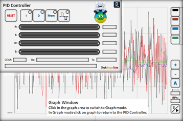
I developed the combined PID controller and graphing tool app using Processing. This took quite a lot of effort, but the end result makes it very easy to change PID controller setting on the fly, as the robot is moving around, simply by moving sliders on the PC screen. You can temporarily save a set of settings you think are close to what you need, make further changes, then recall them if you want them back
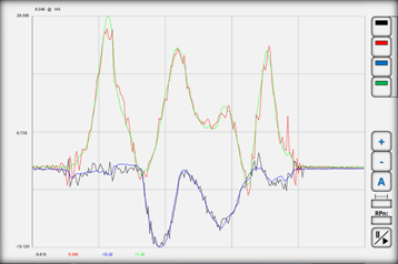
You can switch back and forth between controller adjustment and the graphing tool, so you can also see the effect on data sent from the robot. The tool allows you to access different sets of data from the NANO, just by clicking on a number field. The graph can be dynamically adjusted automatically, showing min/max values or set to specific ranges, and if the graph is paused you can inspect the data points simply by moving the mouse pointer over the graph, to draw on the underlying data.
Design Files
The following files can be downloaded to help you complete this project. Each has a hyper-link and an associated description. Depending on how your web browser is configured the links will either open the files directly into your browser or offer them as downloads.
Circuit Diagram - a drawing of what is seen in the view above. Use it as a guide to wiring up your project. Updated: 08/12/2025.
Wii Controller Diagrams - if you haven’t already made one on other projects this is the controller circuits and build.
Parts List - the things you will need and budget prices.
3-D Parts - images showing you what the 3-D parts look like and the associated hole and tap sizes. Updated: 10/06/2026.
3-D Models - a zip file containing all of the STL files, which you can use with a slicer application. Updated: 10/06/2026.
Software Code - Arduino .ino files. Several folders, one for the robot, one for the Nunchuk remote and one for PID Controller. Updated May’22
PID Controller Info - a pdf outlining a Windows app which enables you to tune the robot and view data over Wi-Fi telemetry.
Demo Functions - pdf explaining the functions available with the button switch, and when using the Wii Nunchuk controller.
Calibration - diagrams and notes created in support of calibrating the robots drive system. Updated: 08/12/2025
Libraries
This project relies on the use of two libraries, Wire.h and SoftwareSerial.h which is included in the IDE set-up. The Wire.h library provides the interface for MPU6050 Gyro and Nunchuk I2C interface. SoftwareSerial.h is used with the wireless transceivers to provide a feed-through function for use with the IDE serial monitor and the PID Controller application. Note that the baud rate is set to 115200 in this project, in order to send high speed data for graphing purposes, which makes the controller incompatible with other projects on this site that run at 9600 baud..
Design Notes:
The following notes will help you understand how the files in this project work or can be used in principle. Each note has a bold heading for quick reference and they are listed in alphabetical order.
.ino Files - the zip file contains several folders, which in turn contain the source code files. Therefore you will need to unzip it to use them. Note, as I use the tabbed interface of the IDE, there are multiple .ino files, one for each tab. All of these must be included for the code to compile correctly.
3-D Models - to be printed at 0.3mm layer height, or smaller. The construction of this design is based on the use of 3 mm and 4 mm nylon countersink screws, with the exception of the metal screws used to house the motors. This leads to a very clean shake-proof solution. You will need to use drills and taps to thread some of the holes.
PID Tuning - As this is the critical part of this project I designed a Windows based app, which makes the tuning of the PID variables very straight forward and something you can do in real time. Once you have arrived at a suitable set of values, for the size of ball you have chosen, you can then hard code them into the NANO code. There is a PDF file provided to explain this process.
Demo - as the role of this robot is to act as a demonstrator, it is possible to switch OFF the ‘I’ and ‘D’ gains in the PID controller by pressing the mode button twice in quick succession. This enables you to demonstrate the effects of the proportional gain term of the PID controller only, which is not sufficient on its own to achieve balance.
Update - the original software release would balance on carpet, but struggled to be stable on a flat surface. In revisiting the project recently, and having made a 4x4 version, I was able to make improvements that now work successfully.
Need more?
If you feel that I haven’t included enough information to allow you to tackle a project of this type then send me an email explaining what you need. Or if you just want to give me some general feedback on this site, or to suggest projects what I might include which would be interesting to you, I’d be pleased to hear from you. I can only respond to questions relating to the work I have published, and the use of components outside of scope can not be considered.
Page updated: 10/06/2026