
- Project
BallBot 4x4 Strider
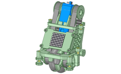
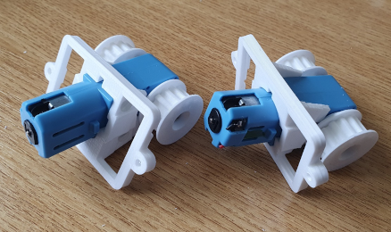
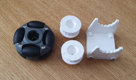
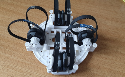
This ball balancing robot is configured with the omni-wheel pairs, in-line with the balls vertical axis; giving the drive system more grip on the balls surface. This in-line arrangement is achieved using twin axle motors and toothed rubber drive belts.
 |
|||||
| Project Overview |
|||||
|
|
|||||
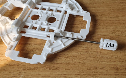
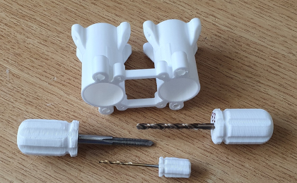
| All of the robot chassis components were produced on my 3-D printer and modelled using 3-D design package. For this design I constructed an assembly of the complete robot, to ensure that all of the parts aligned. This included simple models of all bought components like the motors and H-bridge driver pcb’s, and the omni-wheels. Given the limitations of 3-D printing, the chassis consists of a number of parts screwed together. The top micro plate mounts the majority of electronic components, with easy access to the ESP32 micro for coding updates, and battery removal for charging, at the base. The lower body chassis plate provides a strong platform on which to mount the four DC motors, and H-bridge driver pcb's. You will need small drills, and metric taps, to be able to put threads in some of the holes in this design. The motor mounts require good quality 3-D printer settings. There are also jigs and fixtures to aid with the construction process. |
|||||

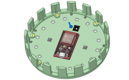
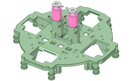
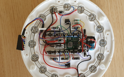
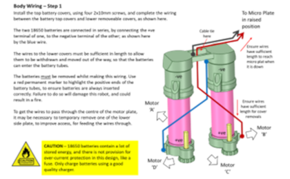
The robot is powered from two 18650 Lithium batteries, delivering 7.4v to the system. An On/OFF switch is mounted on the top plate, which gives you the ability to select power sources. The ESP32 micro constantly monitors battery health, and automatically shuts down the robot, to prevent battery deep discharge. The two push buttons, on the top, are for selecting different operating modes, and for switching display formats.
RGB LEDs, mounted within the top plate can act as a spirit level, used in the initiation of the self-balancing process. The four 8x8 DotStar LED displays present animations, and indicate motors drives, when bvalancing. There is a built-in character set, which can be used to extend the range of animations available. Ensure that you have the hand tools needed to build this robot.
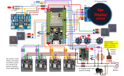
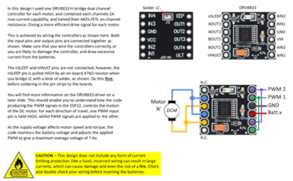
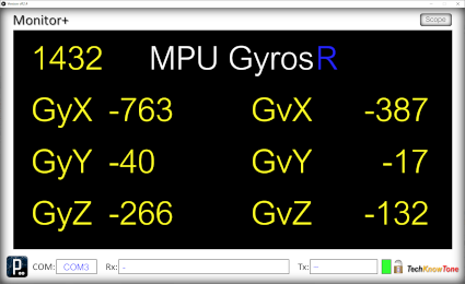
The circuit diagram for the Omni-Bot is shown here on the left, with the ESP32 connected to the four H-bridge drivers, providing high current PWM for the motors, the MPU-6050 3-axis gyroscope and the 16 RGB LEDs, which are connected in a daisy chain fashion. As the motors are only rated up to 6v, I measure the battery voltage and adjust power accordingly. A simple resistor network is used to subdivide the supply voltage so that the ESP32 can measure the voltage remaining in the batteries, which should not be allowed to fall below 3 volts per battery, to avoid damage from deep discharge.
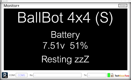
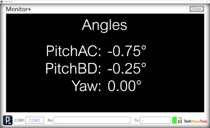
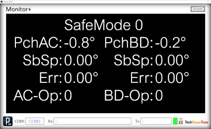
The small display presents status information, and values, depending on the mode of operation. That’s always useful during demonstrations. But much more information is available, when using the Monitor+ app over the ESP-NOW Wi-Fi link.
I developed the Monitor+ display and graphing tool app, using a coding system known as Processing. The features of this app have been further extended whilst developing this project. You can use it to present information on screens, select different screens, and even click on blue text to change values as you go. Your robot can now upload data to the app, which can then be copied within the Windows environment.
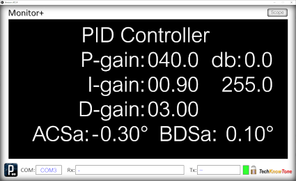
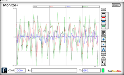
You can switch back and forth between controller adjustment and the graphing tool, so you can also see the effect on data sent from the robot. The Scope tool allows you to access different sets of data from within the ESP32 code, just by clicking on a number field. The graph can be dynamically adjusted automatically, showing min/max values or set to specific ranges, and if the graph is paused you can inspect the data points simply by moving the mouse pointer over the graph, to display the underlying numeric data.
Design Files
The following files can be downloaded to help you complete this project. Each has a hyper-link and an associated description. Depending on how your web browser is configured the links will either open the files directly into your browser, or offer them as downloads.
Circuit Diagram - a .pdf file of drawings and photos, of the build process. Use it as a guide to wiring up your project.
Parts List - the things you will need to buy, budget prices, and web links.
3-D Parts - images showing you what the 3-D parts look like, and the associated hole and tap sizes.
3-D Models - a zip file containing all of the STL files, which you can use with a slicer application.
Software Code - Arduino .ino files, the TFT display setup, and the Monitor+ and 4-channel controller applications.
Calibration - diagrams and notes created in support of calibrating the robots drive system.
Demo Functions - a pdf explaining the functions available with the button switch, and when using the Wii controller.
Libraries
This project relies on the use of these libraries, Adafruit_NeoPixel.h, TFT_eSPI.h, and WiFi.h which need to be included in the IDE set-up. The TFT_eSPI library provide a convenient means of creating text and graphics on the round display. Using sprites for smooth scrolling effects. The Adafruit_NeoPixel library is used for controlling the WS2812B RGB LEDs, on the top plate, and the DotStar panels. The esp_now.h and WiFi.h libraries provides the interface for the Wi-Fi link, which is used on conjunction with a WiFi transceiver. Which is built as a separate project.
Design Notes:
The following notes will help you understand how the files in this project work or can be used in principle. Each note has a bold heading for quick reference and they are listed in alphabetical order.
.ino Files - the zip file contains several folders, which in turn contain the source code files. Therefore you will need to unzip this file, to use them. Note, as I use the tabbed interface of the IDE, there are multiple .ino files, one for each tab. All of them must be included for the code to compile correctly.
3-D Models - to be printed at 0.3mm layer height, or smaller. The construction of this design is based on the use of 2mm steel pozi-drive screws, 3 mm and 4 mm nylon countersink screws. This leads to a very clean shake-proof solution. You will need to use drills and taps to thread some of the holes.
Demo - as the role of this robot is to act as a demonstrator, its main purpose is to show the use of omni wheels, to balance the robot on top of a ball.
Need more?
If you feel that I haven’t included enough information to allow you to tackle a project of this type then send me an email explaining what you need. Or if you just want to give me some general feedback on this site, or to suggest projects that I might include, which would be interesting to you, I’d be pleased to hear from you. However, I can only respond to questions relating to the work I have published, and the use of components outside of scope can not be considered.
Page updated: 19/12/2025