
- Project
Wii Wireless Transceiver
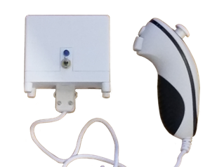
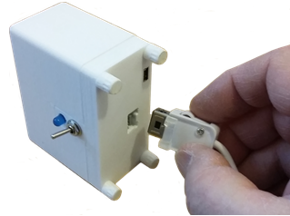
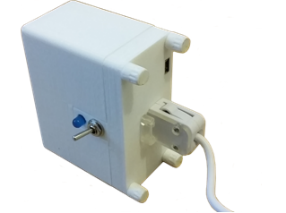
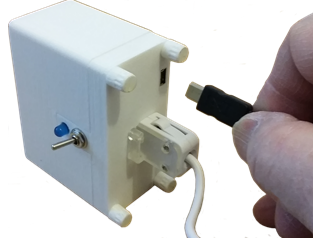
In my earlier versions of a wireless transceiver the Wii Nunchuk was hard-wired into the unit. This version uses a Wii adapter pcb, providing a plug-in method, so you can easily change the controller and compare their performances.
Project Overview
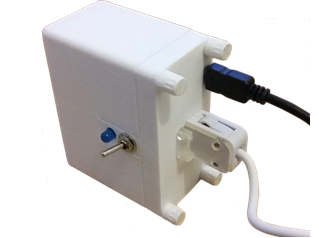
If you are not familiar with my previous projects, like the self-balancing robot, this unit provides a wireless link to your projects, than can operate up to 50 metres away. The Wii Nunchuk controller is a great device as it provides both proportional X/Y joystick control, as well as two buttons and internal 3-axis accelerometers. My earlier versions were hard-wired, making it less than straight forward to change the Nunchuk if needed. With this version the Nunchuk simply plugs into the unit and can easily be removed for storage or if the controller fails.
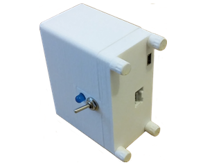
To create room for the Wii adapter pcb I had to change a few things within the original 3-D model. The PP3 9v battery has been rotated by 90 degrees, and the NANO microcontroller has been moved such that its USB connector reaches the surface of the lid.
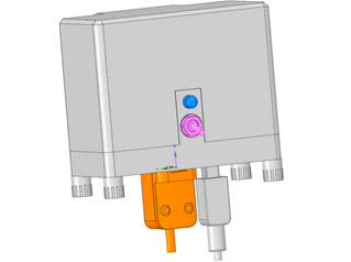
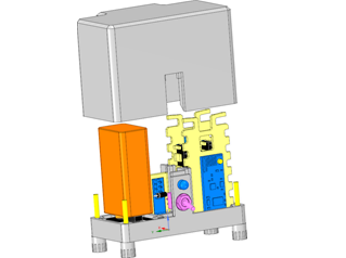
The 3-D design was produced using Design Spark Mechanical, based on an assembly of all of the components, including models of the electronic components, like the Arduino NANO, the wireless transceiver, battery, switch etc.
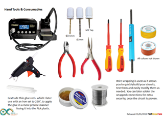
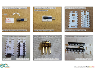
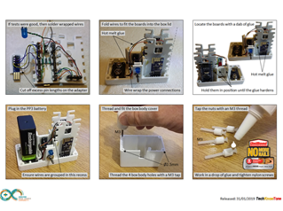
The great thing about 3-D modelling and printing is the accuracy of the component produced, and the way in which the design simply goes together. Once you have printed the parts, all you need to do prior to wiring and assembly is to apply a 3mm thread to some of the holes using an M3 tap. You will also need to use some epoxy resin quick set glue to position the Wii adapter in the slide, and some hot melt glue to hold the items in position.
All of the step by step instructions are contained in the wiring diagrams pdf document.
The build instructions advise you on what hand tools you are likely to need to complete the construction of this project. The vast majority of the wiring was done using a method known as wire wrapping. Whilst the initial cost of the wrapping tool and coloured wire spools will be a small sum, use of this technique makes the detailed wiring much simpler to perform. It has the added benefit of being able to test the design in its wrapped form, and should you find an error it is relatively easy to unwind the wiring and fix the problem.
This is an old technique that was well proven in the early days of developing Apple computers; when the cost of producing a large printed circuit board was quite prohibitive. Since then of course, the cost of producing pcb’s has fallen significantly and is now well within the grasp of the hobbyist. Once the wiring is proven I still solder the joints for added reliability, but that is not absolutely necessary.
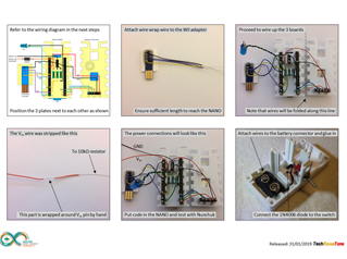
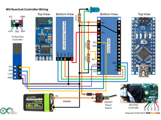
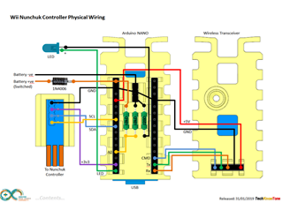
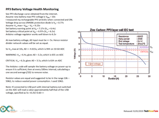
The circuit diagram is shown here on the left, with the Arduino NANO connected to the wireless Transceiver and small Wii adapter pcb. The battery voltage is sourced via the ON/OFF toggle switch and a 1N4006 diode. The diode has been added to prevent accidental damage to the electronics, should the switch be ON and the battery is applied the wrong way round to its connector. The battery voltage is also measure by the NANO via a potential divider circuit to indicate potential power loss to the user. I have included a discharge curve and an explanation of how the limits in the code are derived.
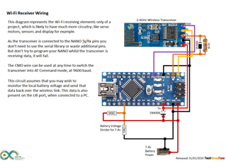
I have also include a circuit diagram for the receiving end of the system, so that you can see how relatively simple it is to add to your project. Note that the received data at the far end is fed directly into the NANO Rx pin. This maximises the number of pins available for your project, whilst providing a mechanism of using telemetry in your project.
Design Files
The following files can be downloaded to help you complete this project. Each has a hyper-link and an associated description. Depending on how your web browser is configured the links will either open the files directly into the browser or offer them as downloads.
Circuit Diagram - drawings of what is seen in the view above, as a guide to wiring up your project.
Parts list - the things you will need and budget prices.
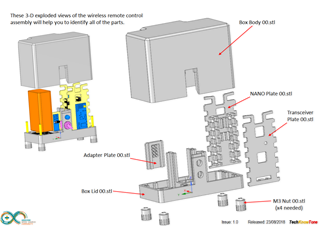
3-D Models - a zip file containing all of the STL files, which you can use with a slicer application.
3-D Parts - a pdf file which identifies the 3-D part STL file references you will need to print.
Software Code - the all important Arduino .ino file which runs the project and ‘Processing’ application. See comments below on coding.
Transceiver - a data sheet on the Open Smart transceiver, explaining how it can be used and configured.
Wii Nunchuk interface - a useful data sheet showing electrical connections and I2C register assignments.
Libraries
This project relies on the use of one library Wire.h, which are included in the Arduino IDE set-up. This library supports the I2C serial bus used to access the Wii Nunchuk controller.
Design Notes:
The following notes will help you understand how the files in this project work or can be used in principle. Each note has a bold heading for quick reference and they are listed in alphabetical order.
.ino File - when you download this file remember to place it in a folder with the same name, otherwise the Arduino IDE will not load it and display an error message.
3-D Models - this design is based on the use of 3mm nylon countersink screws. The models have 2.5mm pilot holes which need to be threaded with a M3 tap to secure the box body to the lid.
STL Model Files - all models are designed to be printed on a 3-D printer with a .4mm nozzle. If you use a printer with a finer nozzle, say 0.3mm, then this may result in the height of the components being slightly less than intended, but I would still expected them to work..
Need more?
If you feel that I haven’t included enough information to allow you to tackle a project of this type then send me an email explaining what you need. Or if you just want to give me some general feedback on this site, or to suggest projects what I might include which would be interesting to you, I’d be pleased to hear from you.