TechKnowTone_Text

- Project

Useless Machine

STEM_Banner_Text

I came across examples of ‘Useless Machines’ on the internet and decided it would be fun to make one for my 1 year old grandson. You too can make this relatively cheap to make toy. Watch the video to see how it works.

Box 01

Project Overview
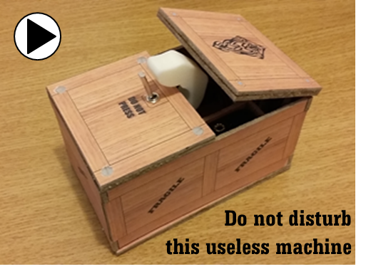
The concept behind all types of  Useless Machines is that it will counter an action you take, and therefore be of no value to you; hence its name. In this case we have a box, with a switch on top of it and a statement saying “Do Not Press!”. Curious folk will of course ignore the warning and press the switch. Shortly after doing so the mechanism inside the box will respond to this, by raising the lid and presenting a finger which returns the switch to its normal off state. It is the thoughtful behaviour of the box which makes it unique and most interesting, and the challenge is to code that behaviour. I’ve included my version here, but you too can modify, extend or replace this code as you see fit. The box incorporates two micro servo motors and an Arduino UNO, plus battery pack. The base of the box is retained with feet that can be unscrewed to gain access to battery compartment for charging. Inside the box is a power ON OFF switch.

Printed Parts 00

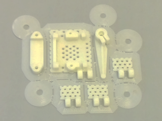
Whilst the box body was designed in PowerPoint and made from 3mm hardboard sheet, all of the internal components were produced in PLA plastic on my 3-D printer, including fasteners, hinges, servo mounts, lid raising lever and the all important finger. These parts were designed in the free 3-D modelling application DesignSpark Mechanical, distributed by RS Components. Depending on the accuracy of your 3-D printer some degree of filing and dressing will be necessary on parts like the lid hinges, to get them to move freely. Small drills and a 3mm tap are also required. The lid of the box has the Count Dracula emblem on it, and attached to the inside of the lid is a darkened laminated image of a scary face, with piercing red eyes, which can be seen as the lid opens.

Depending on the length of the switch lever you select, you may need to modify the finger such that it hits the lever at a high enough point with sufficient force to operate it.

Finger 00

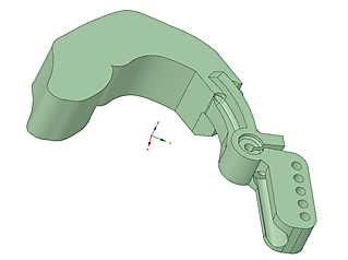
I created the model of the finger by first taking a photo of my own finger, then took that image into the 3-D modeller. I would have preferred it to have had rounded edges, but found that difficult to achieve with my limited modelling skills. The finger design provides a series of holes to which weights could be attached if I had needed to balance it or increase its inertia for when it strikes the toggle switch. But in practise this approach was not needed. Note that I print all of my models with 25% infill, to reduce filament material usage and make them as light as possible.

The finger and its associated servo motor mount off a top plate, through which the toggle switch is also mounted and this is glued to the underside of the fixed lid.

Box Circuit Diagram 00

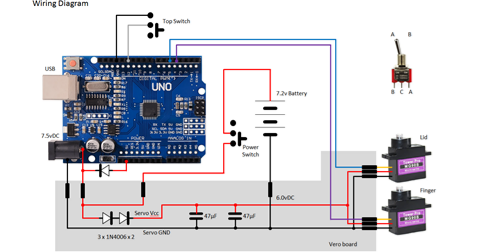
The circuit diagram for this project is shown here on the left, with the Arduino UNO is connected to the two servo motors on the right, with 6v power being fed to the servos from a diode voltage dropping circuit. Servos will normally operate between 4.8v and 6v, but they work much better at the higher voltage. Note that this circuit assumes an input voltage of 7.5v from a power plug or 7.2v from a 6 x AA rechargeable battery pack. If you want to use a higher voltage you will need to modify this circuitry to suit, otherwise you could damage your servos

It is also better not to power the servos from the UNO 5v linear regular, as any dip in supply voltage caused by loading a servo could result in the UNO being reset via its internal brown-out circuitry. Connecting one servo that way for test purposes is fine, but I wouldn’t recommend any more.

The corner fasteners and mount for the power ON/OFF switch were simply glued into position. The fasteners have ribbed sides to increase their surface area for glueing purposes.  All of the 3-D models are provided as STL files, zipped together into one file. They can therefore be used directly with a slicing application of your choice, to create the g-code files for use with a 3-D printer. For my project I used Slic3r to generate the g-code, and it is a free download from the internet.

I also use a free application called Pronterface as a means of loading and viewing the g-code file before sending it to the printer. This gives you information on the amount of material used and most importantly how long it will take to print.
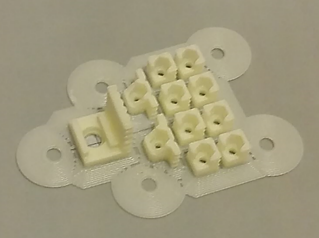
Corner Fasteners 00


Design Files
The following files can be downloaded to help you complete this project. Each has a hyper-link and an associated description. Depending on how your web browser is configured the links will either open the files directly into the browser or offer them as downloads.

Circuit Diagram - a drawing of what is seen in the view above, plus veroboard wiring. Use it as a guide to wiring up your project.
Parts list - the things you will need and budget prices.
Physical Templates - .drawings produced in Ms PowerPoint. Ensure that they do print at the correct size, if used directly on hardboard.
3-D Models - a zip file containing all of the STL files, which you can use with a slicer application.
Servo Calibration - a pdf file depicting how I calibrated the switch and lid servos.
Software Code - the all important Arduino .ino file which runs the project and ‘Processing’ application. See comments below on coding.

Libraries
This project relies on the use of one library, Servo.h, which are included in the IDE set-up. See notes below regarding the need to calibrate your servo motors.


Design Notes:

The following notes will help you understand how the files in this project work or can be used in principle. Each note has a bold heading for quick reference and they are listed in alphabetical order.

.ino File - when you download this file remember to place it in a folder with the same name, otherwise the Arduino IDE will not load it and display an error message.
3-D Models - this design is based on the use of 3mm nylon countersink screws with niloc nuts as fasteners. This leads to a very clean solution as the length of each screw can be easily trimmed adjacent to the nut using wire cutters.
Calibration - When attaching the finger to the servo motor mounted on the fixed lid and the servo which raises the lid arm you will need to determine the angles at which the respect parts touch the toggle switch and lid
.

Page updated: 18/02/2024