
- Project
Reach Robot Mk1
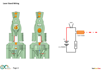
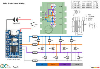
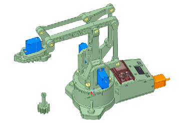
Here I’ve revisited an earlier project to apply a slightly different method of construction and to use an ESP32 microcontroller, which provides much greater scope for features like a display, a much larger memory and the ability to connect it to a wifi network or Bluetooth app. Like its predecessor, here I’m using four miniature digital servos to create a machine which moves objects around a simple workplace. I’ve also include two new machines, with one using a laser diode.
 |
|||||
| Project Overview This version has a display, which gives read-outs on the 4 servos, the MMI to the Wii Classic Controller is greatly enhanced, and I’ve written a Move Trainer app to speed up the development of move sequences, which can now be up to 500 moves. Click on the image opposite to view a video of the robot in action. |
|||||
|
|
|||||
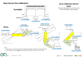
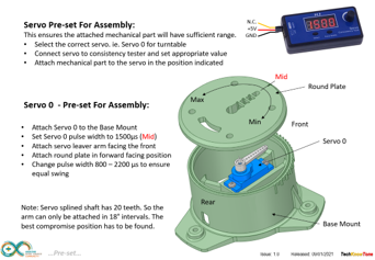
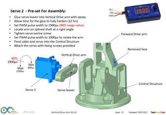
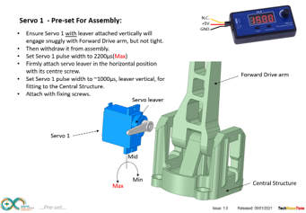
| The design of the mechanical linkages in the reach movement work in such a way that the movement range of the arm, that raises and lowers the head, needs to be constrained in software code, depending on the position of the vertical arm, otherwise lock-up would occur. These physical limitations are controlled within the code, with the vertical arm angle being set first, then the limits for the raising arm are set from that. A calibration diagram is included to explain the angles I determined from my robot. As servo tolerances vary quite widely from one part to another, you will need to calibrate these ranges and enter new values into the code to get this to work correctly. This would also apply to my robot should any of the servos fail and need replacing. I found the digital servos to be faster and more repeatable than the previously used analogue one. |
|||||
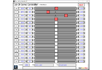
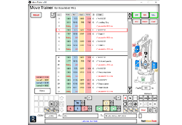
In order to calibrate servos and control the robot, to determine the correct positions of each servo, for moving a gear object around the workspace for example, I developed two Windows PC apps in ‘Processing’. The first one uses 4 of the available 16 channels to determine servo limits during calibration, and the second one acts as a ‘Move Trainer’ where you can create a list of movements, including special commands like jaw clapping, delays, speed control, and branch instructions like Goto and Gosub commands. You can control the robot with keyboard keys or mouse movements.
At any time the list of movements and commands can be uploaded to the robot over the USB serial link, and the robot plays this. You can stop, single step and even go backwards through the movements. The list editor also allows you to enter text as comments, describing what the commands are doing. When ready, the whole list or parts of it can be cut-n-paste into the IDE as part of your code.
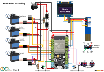
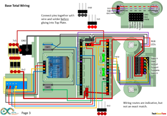
The circuit diagram is shown here on the left, with the ESP32 connected to the four servo motors on the right, with 6v power being fed to the servos from a diode voltage dropping circuit. Servos will normally operate between 4.8v and 6v, but they work much better at the higher voltage. Note that this circuit assumes an input voltage of 7.5v from a power plug or 7.2v from a 6 x AA rechargeable battery pack. If you want to use a higher voltage you will need to modify this circuitry to suit, otherwise you could damage your servos
The I2C interface is used to connect the 64 x 128 OLED display and Wii controller socket to the micro, and two programmable WS2812 RGB LEDs are used to provide status information. The supply voltage is monitored, assuming external batteries are used, and small button switched enable different display modes. The circuits for the two active machines in the workplace are also provided, along with the code for the STM8S micro.
All of the 3-D models are provided as STL files, zipped together into one file. They can therefore be used with a slicing application of your choice, to create the g-files for use with a 3-D printer. For my project I used Slic3r, which is a free download from the internet. I’ve also included an angle gauge, used during the calibration process, and an assembly aid which holds together the controller plates whilst you are wiring them..
The robot is designed to be built in two parts, one being the robot and the other being the control box, so that you have the opportunity of designing your own controller, should you wish to do that. In this design we apply an M3 tap to thread most of the parts, and assemble them using M3 nylon screws. This is rather than using through holes and locking nuts, as in the original design, as I found that the through holes wear very quickly.
Design Files
The following files can be downloaded to help you complete this project. Each has a hyper-link and an associated description. Depending on how your web browser is configured the links will either open the files directly into the browser or offer them as downloads.
Circuit Diagram - a drawing of what is seen in the view above. Use it as a guide to wiring up your project.
Parts list - the things you will need and budget prices.
Physical Templates - drawings produced in Ms PowerPoint. Ensure that they do print at the correct size, if used directly on hardboard.
3-D Models - a zip file containing all of the STL files, which you can use with a slicer application.
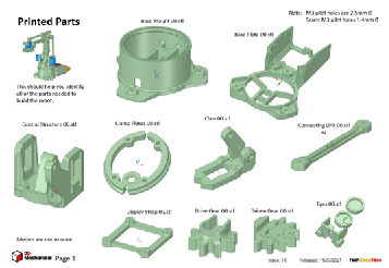
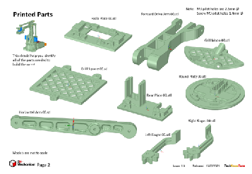
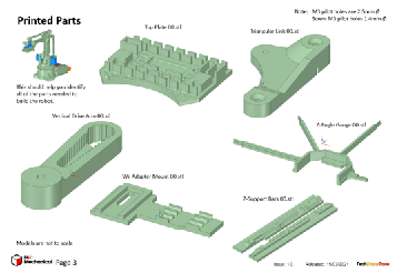
3-D Parts - a pdf file which identifies the 3-D parts, their critical features and how to prepare them for assembly
Parts Assembly - a pdf file which shows you how to assemble the printed parts, with screws, washers and nuts.
Software Code - the all important Arduino .ino file which runs the project and ‘Processing’ application. Updated: vR2. 2024/07/25.
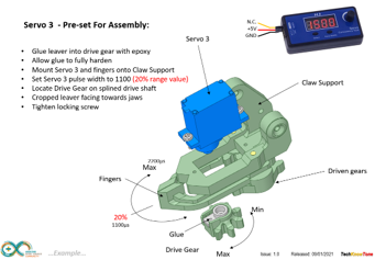
Calibration Record - shows the angles you need to determine and enter into your code to calibrate new servo motors.
Demo Functions - a pdf listing the functions available when using a Wii Classic controller. Updated: 2024/07/25.
Programming - shows you how to use the Windows app to create a simple ‘Move’ program for the Reach Robot.
Accessories - a pdf showing extra 3-D models you can download to create a work area and tasks for your robot.
Wii Classic - a pdf explaining how to use a Wii classic controller with the reach robot.
Libraries
This project relies on the use of six libraries, <Arduino.h>, <HardwareSerial.h>, <ESP32Servo.h>, <Wire.h>, "SSD1306Wire.h", <Adafruit_NeoPixel.h>, "Commands.h" which need to be included in the IDE set-up. If you haven’t used an ESP32 before with the Arduino IDE, then you will need to install the board libraries too. There are several articles on the web that explain this process.
Design Notes:
The following notes will help you understand how the files in this project work or can be used in principle. Each note has a bold heading for quick reference and they are listed in alphabetical order.
.ino File - the .zip file contains the folder ESP32_Wii_Classic_Reach_Robot_00, which in turn contains several .ino files. These are all to be extracted and retained within the same folder, of that name. If you are wondering why there are several .ino files, it is because I use the tabbed interface within the Arduino IDE, and for each tab there is a corresponding .ino file.
3-D Models - this design is based on the use of 3mm nylon countersink screws with niloc nuts as fasteners. This leads to a very clean solution as the length of each screw can be easily trimmed adjacent to the nut using wire cutters.
Calibration Record - It is essential that you undertake a calibration exercised in order to enter the correct values into your .ino file, as servo values can vary widely. Otherwise the mechanical linkages can lock up and servo motors will consume excessive power. Use the keyboard application, or a suitable infra-red remote control to move the robot into the positions indicated.
Serial Port - is used in this design convey readings and commands over the Arduino IDE Serial Monitor, and for general debugging purposes. Being able to see the servo values being applied to each servo is very useful and essential to calibration.
STL Model Files - The forward drive arm has a hidden pocket where the plastic drive leaver from the servo motor is inserted. This is to make the part more printable, and this thin walled pocket can be easily opened up using a hobby knife.
Need more?
If you feel that I haven’t included enough information to allow you to tackle a project of this type then send me an email explaining what you need. Or if you just want to give me some general feedback on this site, or to suggest projects what I might include which would be interesting to you, I’d be pleased to hear from you.
Page updated: 25/07/2024