TechKnowTone_Text

- Project

NANO Circuits

STEM_Banner_Text

With the aim of getting younger students interested in electronics and coding I have developed the following ideas based on the Arduino NANO microcontroller and Terminal Adapter pcb. It’s very low cost and great for developing practical STEM skills. Give this a go, you mghte like it!

Project Overview
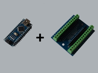
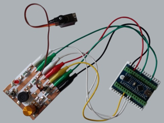
For younger students, traditional bread boarding can take some of the fun out of making your own circuits, and can be a bit fiddly. So here we use the very low cost, but quite capable NANO micro and attach a Terminal Adapter board, to which we can then connect leads with crocodile clips.

Circuits can then be created by students using 6mm copper foil tape on card, following a pre-printed image of the circuit. They then solder their components in place and connect up the NANO board with the crocodile clips. They can then get straight into coding and experimenting!

Use  the sample circuits below to get started. You’ll soon be creating circuits of your own I’m sure.


What You Will Need
Here is the list of essential components needed for this prototyping system, plus if you have access to a 3-D printer, some additional parts that can make the components easier to handle and be more reliable.

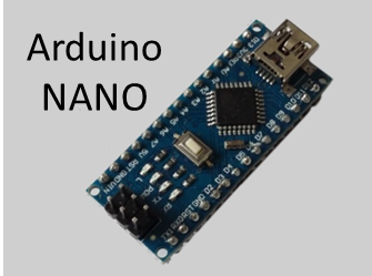
    Arduino NANO - you will need the Arduino IDE for coding and a mini USB cable, with the appropriate drivers installed.
    Terminal Adapter pcb
    Crocodile clip leads - I would recommend that you use specific colours as in GND = Black, 5V = Red, Digital = White, PWM = yellow, Analog = green
    6mm adhesive copper foil tape - this is a good size for circuits, but wider and thinner tape can be used too.
    Hand tools - craft knife, soldering iron, solder, wire cutters, fine nosed pliers

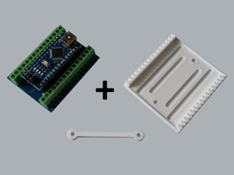
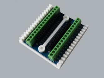
I’ve also provided useful extras, for those with access to a 3-D printer, which will make the system more reliable and easier to handle the components when soldering, as some will get hot!

   Terminal Adapter back plate - this releaves the strain on the wires. Download [here].
    1/4 W resistor mount x10
    12mm Buzzer mount
    15mm Speaker mount
    5mm LED mount x10
    Neopixel mount x1, x3

A .zip file containing the .stl files for all of these mounts can be downloaded [here].

Component_Mounts


Sample Circuits
To get you started I’ve included the following sample circuits for you to try, and I’ll add more as they come to mind. If you have any suggestion for circuits you would like to make, or if you come up with designs of your own, let me know and I’ll include them on this page and give you a mention.


3 Channel LED & Button Switch Strip
You can build this board using the same or different coloured LEDs. In this example I wanted to make a traffic light, so I used a red, yellow and green LED. Note that the forward voltage drop of LEDs is dependant on their colour, so you may want to use different resistor values in order to keep the currents the same and have similar brightness levels. A nominal resistor value is 220 ohms.

The switches are connected to a common GND line and don’t have any pull-up resistors on this board. This is because you can use the pull-up resistors built into the Arduino NANO, by switching them on in your code.

Download files:   Circuit pdf [PDF]   Sample code .ino [INO]
 

Circuit_00

6 Channel LED Strip
This circuit has a common GND connection and a series limiting resistor for each of the 6 LEDs. You can use different coloured LEDs, as I have, or make them all the same if that’s what you have available. If you want to dim the LEDs using the analogWrite() function then you need to connect to the appropriate PWM pins. On the Arduino NANO the PWM pins are D3, D5, D6, D9, D10 and D11.

Nominal resistor values are 220 ohms for red LEDs, if youi want the yellow and green to pass the same current then you will need to use smaller values as their forward voltage is greater than the red.

Download files:   Circuit pdf [PDF]   Sample code .ino [INO]
 

Circuit_01

LED, Switch, Speaker, Servo & Pot. Strip
This circuit board is great for experimenting with a range of devices and code. You have two inputs in the form of the button switch and potentiometer, and three outputs with the LED, speaker and servo motor, plus any data you choose to send to the IDE Serial Monitor.

Note that once the 3-pin strip connector is soldered to the board for the servo motor, it is recommended that you support this with some soft-melt glue or similar adhesive (see in photo). This will ensure that it remains attached to the circuit when the servo motor leads are pulled off.

Download files:   Circuit .pdf [PDF]   Sample code .ino [INO]
 

Circuit_02

Neopixel RGB LED Strip
Programmable RGB LEDs are used in many applications these days as they can display a wide range of colours, including white light and dim primary colours. They are connected together with only three wires in a daisy chain, with serial data being passed along the data line from chip to chip.

The small contacts are quite tricky to solder, but here they are retained in a 3-D printed mount, which makes the process a little easier. • The NANO is capable of writing data to more than a hundred devices, but watch for power losses in the wiring on long runs, which may need capacitors at regular points between power lines and even thicker gauge wiring.

Download files:   Circuit .pdf [PDF]   Sample code .ino [INO]

Circuit_03


Need more?
If you feel that I haven’t included enough information to allow you to tackle a project of this type then send me an email explaining what you need. Or if you just want to give me some general feedback on this site, or to suggest projects what I might include which would be interesting to you, I’d be pleased to hear from you.