
- Project
Magical Sword II
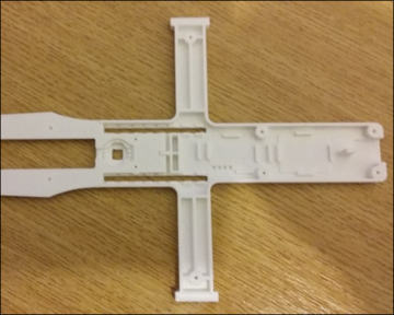
This is a revamp of the original Magical Sword project, which was made out of hardboard and used an Arduino Lillypad micro. In this project I produced the sword using 3D printed part, and gave it a more powerful micro, an ESP32, with Wi-Fi capability.

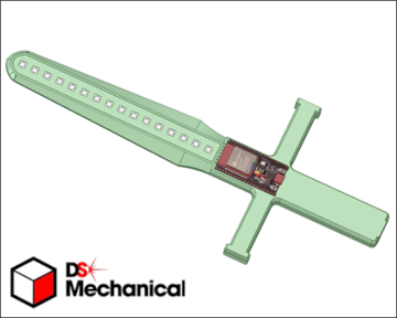
The sword is designed to be powered from an external 7.4v power source; either batteries or a mains adapter. As this makes the sword itself much lighter to use and demonstrate. The microcontroller is clearly visible on the outside, and this makes it easier to apply code to it. I have provided a simple wirings diagram guide, which should give you sufficient information to build this project. Components are either held together with 2-part epoxy glue, or screwed together using M2 x 10mm dolls house screws. I would recommend teh use of wire wrap wire, and a wrapping tool, as that will enable you to test your sword before finally soldering the connections.
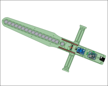
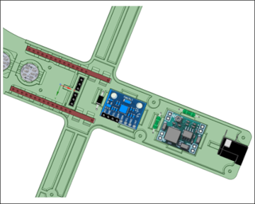
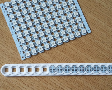
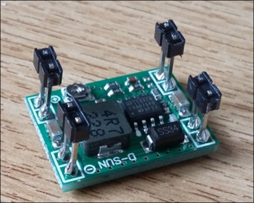
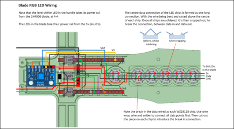
Take great care when soldering the WS2812B RGB LEDs, and glue them into position first to enable soldering. Also observe the legends on the chips, showing the direction of control data and power pins. Adjust the voltage regulator to 5v before plugging in the ESP32 microcontroller. The 5v regulator takes the strain of providing current to the LED strip.
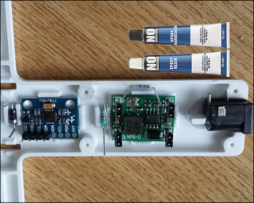
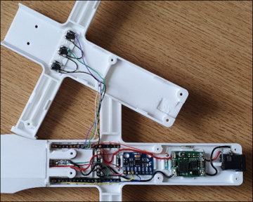


The circuit diagram for the Magical Sword II project is shown here on the left, along with images of the tools and materials you will need, and wiring schematics, The base of the handle houses the three button switches, which are wired separately at first, beofre being connected to the main elecotronics, housed in the handle.
In the original design I did not connect the AD0 address line, on the MPU6050 to the GND connection, as that proved not to be necessary in my case. But I have experienced using the MPU6050 in other projects, and problems occured when this connection was not made. So I recommend retrospecively that you do that.
Design Files
The following files can be downloaded to help you complete this project. Each has a hyper-link and an associated description. Depending on how your web browser is configured the links will either open the files directly into your browser or offer them as downloads. An update has now been included which provides files which enable you to construct the detachable head, seen in the above video.
Circuit Diagram - a drawing of what is seen in the view above. Use it as a guide to wiring up your project.
Parts List- the things you will need and budget prices.
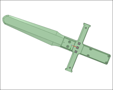
3-D Parts - images showing you what the 3-D parts look like. To be expanded to include the ‘head’ shortly.
3-D Models - a zip file containing all of the STL files, which you can use with a slicer application.
Software Code - the all important Arduino .ino files. Several files for the robot, Nunchuk remote and PID controller app.
Demo Functions - a pdf file, briefly explaining the use of the 3 buttons on the back of the sword.
Libraries
This project relies on the use of two libraries, Wire.h and FastLED.h which are included in the IDE set-up. The Wire.h library provides the interface for I2C devices used in the sword, as in the MPU6050. FastLED.h is used to drive the WS2812B RGB LEDs, providing the coloured patterns. Ensure that your IDE versions match those listed in the code; otherwise problems may occur when compiling the code.
Design Notes:
The following notes will help you understand how the files in this project work or can be used in principle. Each note has a bold heading for quick reference and they are listed in alphabetical order.
.ino File - the Software_Release.zip file contains several folders, which in turn contain the source code files. Therefore you will need to unzip it to use it.
3-D Models - the constructions of this design is based on the use of M2 x 10mm metal screws to hold the case together. You will need a 2.0mm drill and 1.5mm drill for some of the holes.
Demo - as the role of this project is to demonstrate the use of a motion sensor, this pdf document explains the use of the 3 buttons on the back of the sword,
Need more?
If you feel that I haven’t included enough information to allow you to tackle a project of this type then send me an email explaining what you need. Or if you just want to give me some general feedback on this site, or to suggest projects what I might include which would be interesting to you, I’d be pleased to hear from you.
Page updated: 18/05/2025