- Project
Magical Sword
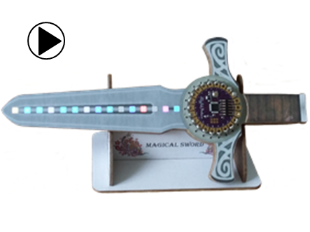
Here’s how I used a LilyPad micro-controller, some programmable LEDs and a 3-axis accelerometer to create a sword that generates light patterns with movement.

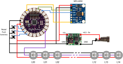
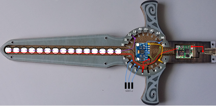
The circuit diagram is shown here on the left, with the Arduino LilyPad connected to the three push switches, the MPU-6050 accelerometer PCB, the 5V regulator PCB, associated two pin power socket and the 15 RGB LEDs.
As LilyPad pin functions are programmable you can choose to wire up the system differently and change the assignments in the code if you wish. You could also make a much longer sword and include more RGB LEDs in your design, conscious that this in turn will consume more power.
This design could also be adapted to e-textile projects, with the components attached to clothing, and the light patterns change as the user moves around the room. Be creative!
Design Files
The following files can be downloaded to help you complete this project. Each has a hyper-link and an associated description. Depending on how your web browser is configured the links will either open the files directly into the browser or offer them as downloads.
Circuit Diagram - a drawing of what is seen in the view above. Use it as a guide to wiring up your project.
Parts list - the things you will need and budget prices.
Physical Templates - drawings produced in Ms PowerPoint. Ensure that they do print at the correct size, if used directly on hardboard.
Software Code - the all important Arduino .ino file which runs the project. See comments below on coding.
Libraries
This project relies on the use of two libraries which can be obtained from the internet, if they are not already included in your IDE. To control the RGB LEDs you will need to use the Adafruit_NeoPixel.h library, and to communicate with the 3-axis accelerometer over the I2C bus you will need to use the Wire.h serial library.
Design Notes:
The following notes will help you understand how this project works in principle. Each note has a bold heading for quick reference and they are listed in alphabetical order.
.ino File - when you download this file remember to place it in a folder with the same name, otherwise the Arduino IDE will not load it and display an error message.
Interrupts - the MPU-6050 uses interrupts to indicate the availability of new accelerometer readings. This method of initiating data transfer over the I2C bus is far more efficient than the overhead of polling the device on a regular basis.
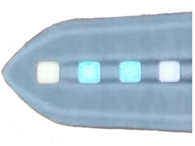
RGB LEDs - in this design I’ve used 15 devices, but noted earlier that many more can be used if you wish, but your array declarations in your code will need to be sized appropriately.
Serial Port - is used in this design convey accelerometer readings to the Arduino IDE Serial Monitor, and for general debugging purposes. Being able to see the gravitational loads being applied to each of the 3-axis is very useful.
Need more?
If you feel that I haven’t included enough information to allow you to tackle a project of this type then send me an email explaining what you need. Or if you just want to give me some general feedback on this site, or to suggest projects what I might include which would be interesting to you, I’d be pleased to hear from you.


