
- Project
TrackBot 2 - A Line Tracking Robot
You will find many line tracking projects on the web. Most are fixed in the way they operate and their performance varies significantly. Having made several designs employing different motor drive schemes, the one I’ve included here is the simplest to make, whilst offering good performance. You can select from seven different speeds and steering responses, and the robot employs automated calibration processes.
Project Overview
This robot uses 3 infra-red sensors to track black taped lines on most surfaces, including laminated A4 sheets. By reading the analogue signals from the infra-red sensors, this gives smoother proportional steering, and the respective black to white thresholds can be determined automatically and stored in flash memory. The use of continuous rotation servo motors reduces the number of parts and greatly simplifies the wiring and construction of the robot. The two button switches provide a means by which the user can select turning and speed ranges independently, and select automated calibration processes for sensor sensitivity, motor balance and line crossing allowances. See the video opposite for these features.

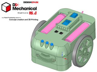
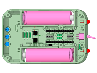
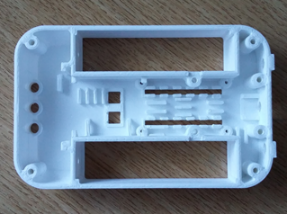
All of the robot chassis components were produced on my 3-D printer and modelled as an assembly using the free 3-D design package from RS Components, DesignSpark Mechanical. Given the limitations of 3-D printing, and the need to access certain features, the chassis consists of a number of layers screwed together. The top plate has compartments for the two batteries, a power switch, two mode switches and three LEDs to mimic the sensor actions.
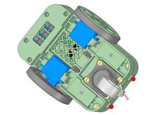
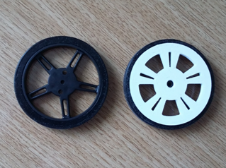
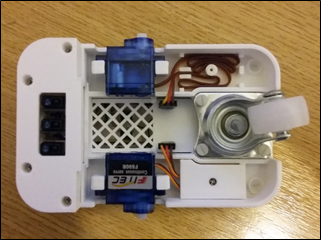
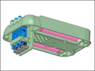
The base plate mounts the servo motors, the rear castor and encloses the electronics and wiring. As the servo wheels are often dark and contrast poorly with the model material, I’ve also included some wheel discs which greatly improve the overall appearance of the robot.
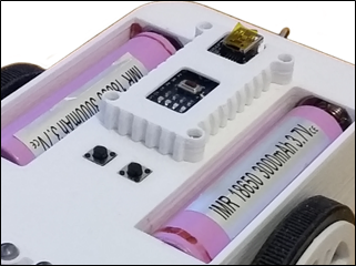
The robot is powered from two 18650 Lithium batteries, delivering 7.4v to the system. An On/OFF switch is mounted on the rear, adjacent to red LED brake lamps. The two push button switches are positioned ahead of the NANO microcontroller, which has a cover over it to protect it from static discharge when handling in a school environment.
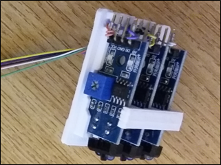
The three infra-red sensors are mounted vertically in the front of the body, with their optical heads being modified such that they are at right-angles to their pcbs. As the code reads the analogue outputs of each sensor in turn, and supports an auto-calibration procedure, we don’t need have access to the small potentiometers on each sensor. It is assumed that the line, made using black insulation tape, is 19 mm wide.

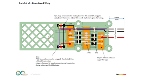


The circuit diagram for the robot is shown here on the left, with the Arduino connected to the three infra-red sensors, and the associated LEDs. To reduce optical cross-talk between sensors, in this design we provide sensor power from digital outputs, so that they can be turned ON and OFF in sequence. The servo motors are connected via 3-pin plugs, and can easily be replaced should failure occur. Diodes are used to drop the supply voltage from 7.2 to 6.0 volts for the servos.
A simple resistor network is used to subdivide the supply voltage so that the Arduino can measure the voltage remaining in the batteries, which should not be allowed to fall below 3 volts per battery, otherwise damage and reduce life will occur.
Design Files
The following files can be downloaded to help you complete this project. Each has a hyper-link and an associated description. Depending on how your web browser is configured the links will either open the files directly into your browser or offer them as downloads.
Circuit Diagram - a drawing of what is seen in the view above. Use it as a guide to wiring up your project.
Parts List - the things you will need and budget prices.
3-D Parts - images showing you what the 3-D parts look like and the associated hole and tap sizes.
3-D Models - a zip file containing all of the STL files, which you can use with a slicer application.
Software Code - Arduino .ino files which run the project. Several folders, one for the robot, one for the Nunchuk remote and one for PID Controller.
Demo Functions - a brief explanation of how to control the robot using the button switches.
Libraries
This project relies on the use of two libraries, EEPROM.h and Servo.h which is included in the IDE set-up. The EEPROM.h library enables the code to recall and store variables from flash memory, so they are not affected by reset or power-off conditions. Servo.h is used, as one might expect, to send control pulses to the two servo motors on a regular basis.
Design Notes:
The following notes will help you understand how the files in this project work or can be used in principle. Each note has a bold heading for quick reference and they are listed in alphabetical order.
.ino File - the zip file contains several folders, which in turn contain the source code files. Therefore you will need to unzip it to use them.
3-D Models - the constructions of this design is based on the use of 3 mm and 4 mm nylon countersink screws, with the exception of the metal screws used to house the motors. This leads to a very clean shake-proof solution. You will need to use drills and taps to thread some of the holes.
Demo - as the role of this robot is to act as a demonstrator, it is possible to run calibration procedures and set the turning and speed values using the button switches..
Need more?
If you feel that I haven’t included enough information to allow you to tackle a project of this type then send me an email explaining what you need. Or if you just want to give me some general feedback on this site, or to suggest projects what I might include which would be interesting to you, I’d be pleased to hear from you.