
- Project
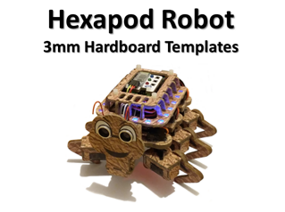
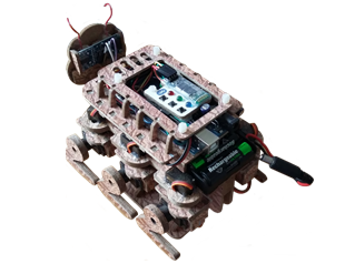
Hexapod - A 6-legged walking robot, named Hex
I created this interesting robot some time ago. It’s based on an Arduino MEGA board and made out of 3mm hardboard, from pieces designed in PowerPoint. If you don’t have access to a 3-D printer then this is a good alternative. Why not make one too!
Project Overview
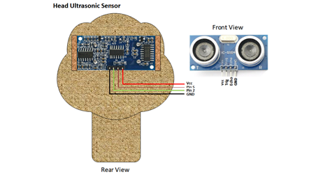
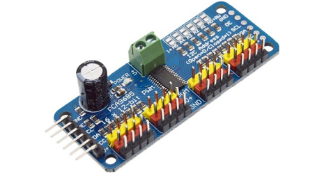
These days there are many examples of Hexapods on the internet, normally built from plastic parts sourced from 3-D printers. This design uses a very different approach, being created in 2-D using PowerPoint, then cut from 3mm hardboard using a fret saw. There are 13 MG90S micro servo motors used in this design, which are driven from a 16 channel PWM driver board, over the I2C bus, to reduce the load on the microcontroller. The coding challenge was quite complex as I incorporated an ultrasonic distance sensor in its rotating head, which makes way for fully autonomous movement. So this design was based on using an Arduino MEGA board for maximum code space. It has button switches to select modes of operation, but it can also be controlled from a mobile phone app using Bluetooth. Click the image to the right to watch a short video of my Hexapod in action -->

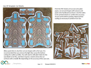
All of the parts needed to make this robot, including its stand, were designed in PowerPoint and made from 3mm hardboard. This method is quite accurate and allows you to included in your design a wide variety of graphics, that would otherwise prove to be very difficult in other manufacturing methods like laser cutting and 3-D printing. Many of the parts are made from two pieces glued together back to back, which makes for a very strong 6mm material.
The servo motors and other parts which may need to be removed at a later stage were glued in place using soft melt glue. This can be applied directly from a glue gun, but I prefer a method in which the glue is first extruded into long thin rods in a shallow tray of water, then applied like a welding rod using a temperature controlled soldering iron. The glue can easily be removed at any time by reheating it with an iron and removing it with cotton buds. As servo motors can fail unexpectedly this is a good method to adopt in practise.
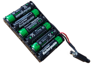
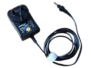
The robot is powered from a 7.2v Lithium battery pack, made up from 6 x AA rechargeable batteries. The power plug from this pack plugs directly into the Arduino MEGA power socket, so there is no need for a separate ON/OFF switch. During prolonged software development these batteries can easily be substituted by a 7.5v DC mains adapter.
A lot of current is drawn from the batteries by the servo motors when the robot it driven from rest to its free standing position, and this can cause a dip in the supplied voltage which is sufficient to reset the microcontroller. To prevent this electrolytic capacitors are needed to absorb this current spike. The robot also has an array of multi-coloured RGB LEDs around its body, which all in all makes the robot quite power hungry.
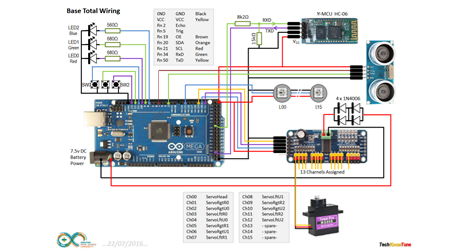
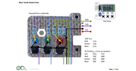
The circuit diagram for the Hexapod is shown here on the left, with the Arduino connected to the thirteen servo motors via a 16 channel PWM pcb. The Bluetooth transceiver requires resistors to perform level shifting for its 3.3v input, and the 16 RGB LEDs are simply connected in series with 5v and GND rails.
I have shown you how to wire up the 3 button board, which mounts the Bluetooth transceiver and status LEDs.
Given the power needed to move the legs of the robot, particularly when standing up, I used 1N4006 diodes as a voltage dropper to feed the 16 channel PWM pcb with 6 volts; the maximum for these servos. Some electrolytic capacitors may be need to sustain the Arduino power, as surges in current for the servos can result in the micro resetting.
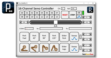
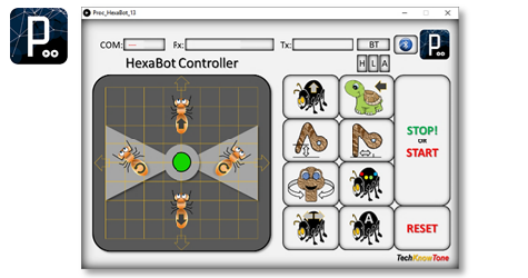
Given the number of servos involved, and the need to calibrate their positions and motion, I decided to write a servo control app using Processing for Windows. This then moved onto an app for controlling the robot; as in getting it to stand up, sit down, turn ON/OFF LEDs and behave autonomously, again written in Processing.
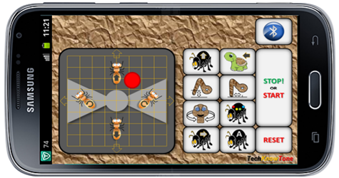
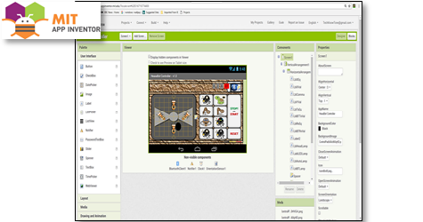
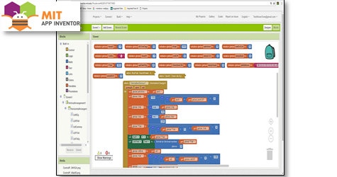
Then, once happy with that I finally moved on to developing an app using MIT App Inventor 2, which you can use to develop Android based apps for your mobile phone or tablet device. This free tool, now provided by Google, has both a screen designer and code block editor. As it supports the connection of Bluetooth devices it was ideal for this application, and I found it relatively easy to learn and use.
Design Files
The following files can be downloaded to help you complete this project. Each has a hyper-link and an associated description. Depending on how your web browser is configured the links will either open the files directly into your browser or offer them as downloads.
Circuit Diagram - drawings of what is seen in the view above. Use it as a guide to wiring up your project.
Parts List- the things you will need and budget prices.
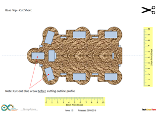
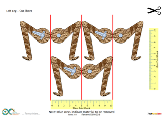
Design Templates - a pdf file containing all of the 2-D drawings used to create the 3mm hardboard parts.
Software Code - the all important Arduino .ino files which run the project, along with the Processing app needed for setup.
Demo Functions - two slides explaining the button and app control functions.
Libraries
This project relies on the use of four libraries, Wire.h, SoftwareSerial.h, Adafruit_PWMServoDriver.h and Adafruit_NeoPixel.h which need to be included in the IDE library manager. The Wire.h library supports the I2C interface used by the 16-channel PWM controller. SoftwareSerial.h is used to support communications with the Bluetooth transceiver. Adafruit_PWMServoDriver.h functions are used to control the 13 servo motors and the Adafruit_NeoPixel.h library is used to send colour data to the 16 RGB LEDs.
Design Notes:
The following notes will help you understand how the files in this project work or can be used in principle. Each note has a bold heading for quick reference and they are listed in alphabetical order.
.ino File - the zip file contains several folders, which in turn contain the source code files. Therefore you will need to unzip it to use it.
Calibration - You will need to spend some time calibrating the servos. This includes presetting them prior to attaching limbs, as well as determining their range of movement, such that the legs are positioned correctly and move in harmony.
Demo - as the role of this robot is to act as a demonstrator, it is possible to set it into several modes of operation. All of which can be controlled from the button switches mounted on the top of the robot.
Need more?
If you feel that I haven’t included enough information to allow you to tackle a project of this type then send me an email explaining what you need. Or if you just want to give me some general feedback on this site, or to suggest projects what I might include which would be interesting to you, I’d be pleased to hear from you.