
- Project
Halloween - A Musical Novelty
The youngsters in our family really like to get involved in the Halloween festivities, so I thought I would join in by making this animated musical novelty. Copy this or grab your own graphics from the web to make something spooky!
Project Overview
The principal behind this projects is a standalone item that will periodically come to life. As it wakes up the fire inside the pumpkins lantern flickers, increases in brightness and then turns into a spooky colour. Shortly after that one of 12 Halloween tunes will be played, whist the skull rotates from left to right and the eyes flash in sequence with the music. Once the tune has been played the skulls centralises, then the flames in the pumpkin lantern return to normal before slowly going out. You can copy this design directly from the files provided or you can use the principals to design your own. You can add more animation with addition servo motors and or linkages, add more NeoPixel RGB LEDs as lights, and change the tunes to whatever you desire. I’ve also include information on how you translate musical score sheets to note references in the arduino sketch. Click to watch the video -->


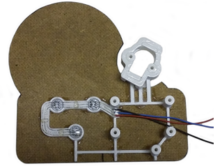

This design benefits from good graphics brought together in PowerPoint, then pasted onto hardboard and cut out with a fret saw. The skull and the pumpkin are separate pieces from the back plate, as the skull needs to be mounted on a servo motor for movement, and the pumpkin has its eyes and mouth piece removed to let light shine through from the NeoPixel LEDs mounted on the rear. The pumpkin was then printed again on a sheet of sticky backed paper, which was then laminated. When you then cut out the pumpkin and separate the two sides of the laminated piece you get a self adhesive plastic coated membrane which works very well as a lens for the back lights.
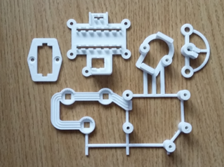
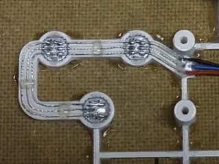
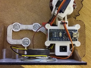
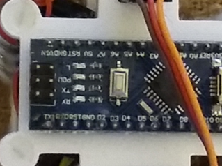
The rest of the design was modelled in 3-D and printed in PLA, to provide mounts for the servo motor and the Nano microcontroller. The NeoPixel LEDs were mounted in printed cups using soft-melt glue, with the three tinned wires being fed round a track way to prevent them from touching each other. Soft-melt glue was also used to secure the 64 ohm speaker in place. 3 mm Nylon screws hold the assembly together and the wooden parts are glued together with UniBond No More Nails. As this glue sets clear and is water resistant I also brush it over the graphics to give them a tough gloss finish.
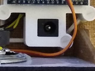
This design is intended to be powered from either a 6 x AA battery pack or a 7.5v DC mains adapter, plugged into the standard Arduino style socket. On power-up the LEDs will light momentarily, the skull servo motor will centralise and the speaker will squeak, to indicate all is well. The unit then appears to go into a state of inactivity for several seconds before the first sequence starts. The simulated flames in the pumpkin will light up and flicker, then change to a random colour after a few more seconds. Shortly after that the first tune will be played, whilst the skull rotates from side to side, with the red LED eyes blinking to the beat of the music. Once the tune is finished the skull will centralise and the flames in the pumpkin will return to a normal colour before fading away. Seconds later the cycle will start over again with the next tune in the sequence being played. In all the code contains 12 tunes, which at first are played in sequence, but then randomly after that.
Two additional modes are accessed via the RESET button, the first with increased sound volume and the second with no sound or movement. This feature uses the EEPROM memory. If the unit is simply powered up or RESET it will always play the default low volume fully animated sequence. However if you press the RESET button again whilst the on-board LED is flashing, the NANO can record that in EEPROM memory. So one additional RESET whilst the LED is flashing will give mode two, and a third RESET will give the third mode of operation.

The circuit diagram for this project is shown here on the left, with the NANO connected to the three NeoPixel LEDs, two red LEDs, a speaker and a servo motor for the skull. Power is fed to the servo motor from a diode voltage dropping circuit. Servos will normally operate between 4.8v and 6v, but they work much better at the higher voltage. Note that this circuit assumes an input voltage of 7.5v from a power plug or 7.2v from a 6 x AA rechargeable battery pack. If you want to use a higher voltage you will need to modify this circuitry to suit, otherwise you could damage your servo motor. The diagram would be the same for a UNO or MEGA board.
The use of the Servo.h library disables PWM on pins 9 and 10, so I had to include code in the main loop to dim the eye LEDs by simulating PWM on those pins. You could use different PWM pins and remove this code option if you wish.
Design Files
The following files can be downloaded to help you complete this project. Each has a hyper-link and an associated description. Depending on how your web browser is configured the links will either open the files directly into the browser or offer them as downloads.
Circuit Diagram - a drawing of what is seen in the view above. Use it as a guide to wiring up your project.
Parts list - the things you will need and budget prices.
Physical Templates - print and use these images to create the backdrop, pumpkin and skull parts.
3-D Models - a zip file containing all of the STL files, which you can use with a slicer application.
Software Code - the all important Arduino .ino file which runs the project and ‘Processing’ application. See comments below on coding.
Music Ref Sheet - if you are unfamiliar with music notation, this should give you enough to enter simple tunes from score sheets.
Music Score Sheets - these are the 12 tunes coded into this project. Use of the reference sheet above will help explain how this is done.
Libraries
This project relies on the use of three libraries, Servo.h, EEPROM.h and Adafruit_NeoPixel.h, which are included in the IDE set-up. See notes below regarding the need to calibrate your servo motor.
Design Notes:
The following notes will help you understand how the files in this project work or can be used in principle. Each note has a bold heading for quick reference and they are listed in alphabetical order.
.ino File - the zip file contains a folder, which in turn contains the source code files. Therefore you will need to unzip it to use it..
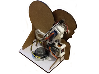
3-D Models - this design is based on the use of 3mm nylon countersink screws. The skull is effectively connected to the servo motor with the use of soft melt glue. You will need to attach the inner part to the servo motor drive shaft prior to clamping the servo motor in place. The the skull mounting for the LEDs and the servo drive attachment are held together with soft melt glue.
Calibration - Prior to attaching the skull mount mentioned above you should first centralise the servo. This can be simply done by installing the code and running it briefly, as the start-up routine centralises the servo, then remove power before a tune is played to prevent the skull animation from starting. Whilst servo motors vary in terms of angular value, the above should give you a working solution. But further calibration can be undertake using a servo motor calibrator or similar software solution.
Need more?
If you feel that I haven’t included enough information to allow you to tackle a project of this type then send me an email explaining what you need. Or if you just want to give me some general feedback on this site, or to suggest projects what I might include which would be interesting to you, I’d be pleased to hear from you.