
- Project
Fake TV 2 - A Burglar Deterent
One of the first projects I did when learning about Arduino was to make a Fake TV simulator, using LED lamps from a torch. It’s worked well for several years, so now I’ve revisited the project to bring it up to date using programmable RGB LEDs and an ESP8266 IoT micro. This really is a useful thing to have in your home.
 |
|||||
|
Project Overview |
|||||
|
|
|||||
|
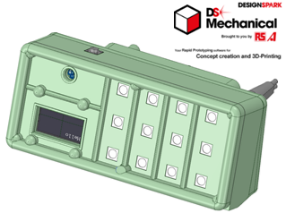
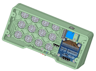
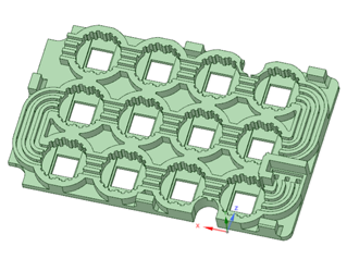
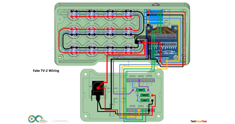
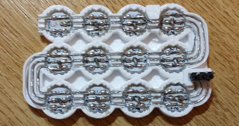
All of the units case components were produced on my 3-D printer and modelled as an assembly using the free 3-D design package from RS Components, DesignSpark Mechanical. Given the complexity of mounting and wiring the WS2812B RGB LEDs, they are first placed in a specially designed tray, which aids the routing of the wiring, and it in turn is then glued into the body of the unit. A clear empty laminated sleeve is first trimmed, then placed between the body and the front fascia to act as a protective dust film. Sand or file its edge to match precisely casing. The push button mounted on the top of the unit is all that you need to control the unit and its settings. |
|||||
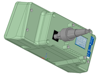
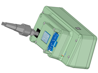
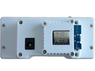
The unit is powered from a wall adapter using either a 5v micro USB connection or a 2.1mm centre positive jack plug, plugged in at the rear of the unit.
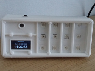
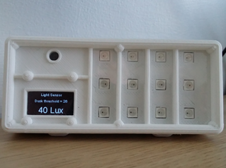
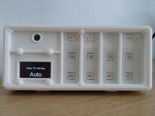
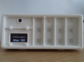
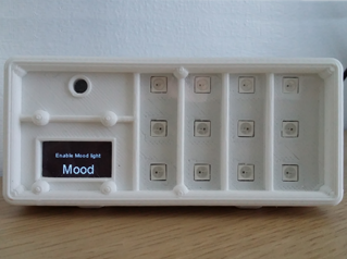
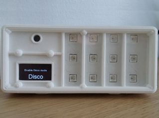
On power up the unit will connect to your home network using the routers SSID and password you have assigned in the code, and then start in clock mode. Pressing the top button will cycle through the supported modes from Lux meter to Disco screens. To modify settings you simply hold down the button on the respective screen until it enters change mode. LED brightness levels can be set over a wide range, and the Fake TV on time can be set from 1 to 6 hours, auto or off.
In the unlikely event that you don’t have a home network then the code can easily be modified to use the light meter as the triggering function; just like my previous one.
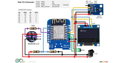
The circuit diagram for the unit is shown here on the left. For ease of construction I use wire wrapping to complete the connections between components like the ESP8266 and the display and sensors. You can then test the unit before soldering the connections if you like.
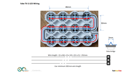
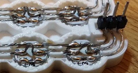
The WS2812B LEDs were wired using stripped multi-strand wire, which is first tinned using a soldering iron and solder to stiffen it. The outer power wires GND and +5v run from one device to the next like bus bars. The centre signalling connection needs to be broken at each LED, so I use a method of kinking the wire, whilst soldering it to the pads; then cropping out the kink with a pair of wire cutters afterwards, as seen in the photos to the left.
Design Files
The following files can be downloaded to help you complete this project. Each has a hyper-link and an associated description. Depending on how your web browser is configured the links will either open the files directly into your browser or offer them as downloads.
Circuit Diagram - a drawing of what is seen in the view above. Use it as a guide to wiring up your project.
Parts List - the things you will need and budget prices.
3-D Parts - images showing you what the 3-D parts look like and the associated hole and tap sizes.
3-D Models - a zip file containing all of the STL files, which you can use with a slicer application.
Software Code - Arduino .ino files which run the project. Several folders, one for the robot, one for the Nunchuk remote and one for PID Controller.
Libraries
This project relies on the use of five libraries, Adafruit_NeoPixel.h, BH1750FVI.h, EEPROM.h, SSD1306Wire.h, and Wire.h of which some will need to be installed in IDE using the library manager. The Adafruit_NeoPixel.h library is needed to control the RGB LEDs. The BH1750FVI.h library is needed to communicate with the light sensor over the I2C bus. The EEPROM.h library enables the code to recall and store variables from flash memory, so they are not affected by reset or power-off conditions. The SSD1306Wire.h library is used to send information to the 128 x 64 OLED display over the I2C bus. And the Wire.h library is needed for the I2C bus interface.
Design Notes:
The following notes will help you understand how the files in this project work or can be used in principle. Each note has a bold heading for quick reference and they are listed in alphabetical order.
.ino File - the zip file contains a folder, which in turn contain the source code files. Therefore you will need to unzip it to use them.
3-D Models - the constructions of this design is based on the use of 2 x 10 mm countersink self-tapping screws. This leads to a very clean shake-proof solution. You will need to use drills to open up some of the holes, which may print at a smaller diameter.
Need more?
If you feel that I haven’t included enough information to allow you to tackle a project of this type then send me an email explaining what you need. Or if you just want to give me some general feedback on this site, or to suggest projects what I might include which would be interesting to you, I’d be pleased to hear from you.