- Project
Christmas Novelty
Here’s how I used a speaker and some LEDs to make an interesting animated novelty for use at Christmas. Something that you can make for yourself or as a gift for a parent or relative.
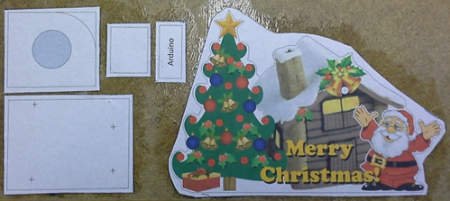
Once the five parts have been cut from the hardboard they can be glued together. Note that I drilled the holes for the LEDs before cutting the profile as they are close to the edge and the material could fail if you cut the profile before drilling the holes. The parts are simply glued together using a strong PVA based wood glue. I also tend to paste the glue around the edges of the material as this adds significant strength and robustness to the finished design.
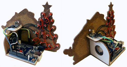
In the photo you can see views of the rear of the project with all of the items in place, including the wiring of the LEDs, infra-red sensor and speaker.


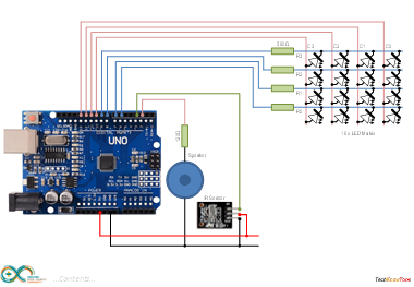
The circuit diagram is shown here on the left, with the Arduino UNO on the left and the speaker in the centre. Note that as the digital output of the Arduino can not provide a large current we need to limit what is drawn by the speaker using a series resistor. I would recommend that the circuit impedance is no less than 120 ohms to prevent damaging the UNO. Whilst I used an 8 ohm speaker, this is not ideal as most of the electrical energy is absorbed by the resistor. A better solution, and one that would appear louder, would be to use a 64 ohm speaker, which would then allow you to reduce the value of the series resistor accordingly.
The infra-red receiver has only 3 connections, GND, +5v and Signal. In my design I wanted to use 16 LEDs, which if wired directly would have required 17 wires and 16 limiting resistors. To reduce the wiring and resistor count I therefore decided to connect them as a 4 x 4 multiplexed array. This approach reduces the wiring to 8 wires and uses only 4 resistors as seen. It does however mean that your code needs to effectively scan the array with a constantly changing pattern in order to illuminate all of the LEDs.
Design Files
The following files can be downloaded to help you complete this project. Each has a hyper-link and an associated description. Depending on how your web browser is configured the links will either open the files directly into the browser or offer them as downloads.
Circuit Diagram - a drawing of what is seen in the view above. Use it as a guide to wiring up your project.
Music Ref Sheet - use this to aid you in the entry of your musical tunes when reading score sheets.
Parts List - the things you will need and budget prices.
Physical Templates - drawings produced in Ms PowerPoint. Ensure that they do print at the correct size, if used directly on hardboard.
Software Code - the all important Arduino .ino file which runs the project. See comments below on coding.
Design Process - notes to support a classroom design activity.
Design Code - a zip file containing the .ino example files discussed in the ‘Design Process’, plus a generic solution which excludes LED multiplexing.
Sheet Music - a zip file containing 10 pdf files of sheet music. Including ‘Deck The Halls’, ‘Jingle Bells’, ‘Silent Night’, etc
Libraries
This project relies on the use of two libraries which were obtained from the internet. Whilst I began by using the libraries built into the IDE, which got me going, I then discovered that they were incompatible with one another due to their conflicting use of hardware interrupts. Fortunately however I did find libraries that would work together from the GitHub site. To ensure that you are using the same libraries as I have, you can download them as .zip files from this server:
Arduinio-IRremote - v2.01 infrared library by Ken Shirriff
NewTone - v1.0 tone library by Tim Eckel.
Alternatively go to the GitHub web site to check for a later version, if one exists here: https://github.com/z3t0/Arduino-IRremote
Design Notes:
The following notes will help you understand how this project works in principle. Each note has a bold heading for quick reference and they are listed in alphabetical order.
.ino File - when you download this file remember to place it in a folder with the same name, otherwise the Arduino IDE will not load it and display an error message.
Interrupts - the melody library and the infr-red libraries use hardware interrupts to precisely control timing. I discovered that the toneMelody library in the IDE used the same interrupts as those used by the infra-red receiver library. So I used the library by Tim Eckel which uses different hardware interrupts to avoid this conflict. Ensure that you have these libraries installed on your system or you will get compiler errors.
Multiplexed LEDs - this method was used to reduce the number of wires and resistors needed to drive the 16 LEDs. However the code must contain a software scanning routine which effectively takes each column wire HIGH in turn, having first pre-set the Row wires to a LOW (ON) or HIGH(OFF) state. The desired state of each LED is held in a 4 x 4 array. To turn a LED ON you simply place a 1 value into one of the array elements. This process occurs whilst each note of the music is being played. As the inter-note delay period is measured in milliseconds it made sense to drive the LED column wires at a 1 millisecond interval.
Musical Score - the sample toneMelody sketch file built into the Arduino IDE, offered by Tom Igo, plays a simple 8 note melody from an array variable. In this project I wanted to play several melodies of different lengths and up to 80 notes. The array used is therefore much larger, with a separate variable being used to keep count of the number of notes loaded into it. Melody functions are called to load the array variables prior to playing each melody.
Serial Port - is used in this design for two purposes. One is to return the codes received from the IR sensor to confirm what has been received. You can use this feature to determine the codes sent, if you use a different remote control to the ones I used. You can also send key values to the Arduino over the USB link as it will respond to individual keys like ‘1’, ‘3’, ‘<’ etc, just like on the keypad.
Need more?
If you feel that I haven’t included enough information to allow you to tackle a project of this type then send me an email explaining what you need. Or if you just want to give me some general feedback on this site, or to suggest projects what I might include which would be interesting to you, I’d be pleased to hear from you.

